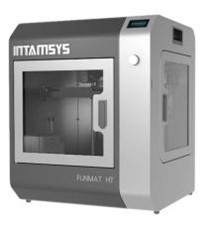
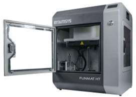
打印机用户手册
FUNMAT PRO HT
智能多材料工业级3D打印机

High Performance Functional Materials 3D Printe
¶ 免责声明
请认真阅读本用户手册内容。未遵从本用户手册执行可能导致人身伤害、不良后果或机器损坏。请确保
任何使用该款3D打印机的用户充分理解本用户手册内容,发挥打印机最大效用。
产品的安装、搬运、贮存、使用或处置超出我们的控制,可能也超出了我们的认知范围。由于此原 因或其他原因,对于因安装、搬运、贮存、使用或处置本产品产生的、或者以任何方式与之相关的
损失、人身伤害、设备损坏或费用,我们概不负责,并明确否认此类责任。
¶ 使用
INTAMSYS 3D 打印机是使用熔融沉积成型技术处理各种功能塑料,例如PEEK, PEI, ABS, PC, NYLON 或 TPU 等,以达到商业性目的。INTAMSYS 3D 打印机的工作精度和打印速度使得其最适合处理概念 模型、功能原件或小批量产品。尽管可以使用Intamsuite软件打印高标准的3D模型,但用户仍然需 要对打印产品的实际结果是否符合预期负责。INTAMSYS 3D打印机是开放式平台机器,这意味着 您可以使用任何第三方耗材进行打印,但为了得到最好的打印效果,我们推荐您使用INTAMSYS认
证的耗材,因为它们就是为INTAMSYS 3D打印机定制的。
¶ 目录
¶ 01 安全规范
¶ 安全
¶ 转运安全
此款打印机非常沉重,所以在拆封机器或移动机器时,需要他人帮助。另外,打印机需放置在
平整地面上,任意方位都应有足够空间保证自由操作。
¶ 电气安全
电源应符合CE 标准,且有短路保护、过载保护、漏电保护及高温保护。仅能使用INTAMSYS提供
的电源电缆工作。
¶ 机械安全
打印机具有很多移动元件,而步进电机的功率并不足以造成严重损伤。但我们依然建议您仅在切断电源
后进行打印机内部维护工作。
¶ 高温安全
FUNMAT HT配有全金属喷嘴,高温平台和加热腔室。在打印需要加热腔室温度至90℃的功能材料 时,热量会传导至机器外框架, 所以我们建议您在打印过程中不要触碰打印机。打印工作时,喷 嘴温度最高可达450℃, 热床最高温度可达160℃ 。因此,我们强烈建议您在打印机工作时不要触碰喷嘴和热床。
另外,在打印机冷却前避免打开前门和天窗。
¶ 危险


本手册中每条安全警示信息前都有安全警示标志符号。这些标志表示将对您的人身、产品、财产造成潜在危险。
警告:不要让机器在工作时处于无人看管状态。
警告:维护前请关闭电源。
警告:打印机工作时不要触碰喷嘴或热床。
警告:打印完成后,请使用铲刀取出工件。
警告:打印机包含可以引起损伤的移动元件。在打印工作进行时,千万不能进入打印机内部作业。
警告:存在短路风险,开启电源时不能触碰任何电气元件。
注意:紧急情况下,可以在插座处断开电源。
注意: 打印机工作时将会融化塑料耗材,并散发出塑料气味。确保打印机放置在通风良好的区域。
¶ 02 介绍
¶ 关于Intamsys
关于Intamsys
INTAMSYS ( INTelligent Additive ManufacturingSYStems的缩写)是工业级3D 打印机制造商,专门从事高 品质热塑塑料的3D 打印工作。公司由一支经验丰富、专业从事高精度机械工业设备的工程师团队组 成。公司最先进的设备FUNMAT 3D 打印机专为打印高性能功能材料而设计,并且物美价廉。FUNMAT 就 是功能材料(functional materials) 的英文缩写。INTAMSYS 致力于最高的设计规范和质量标准,旗下 3D 打印机已经取得了FCC 和 CE 认证。如今,INTAMSYS已被全世界范围内的客户认可,无论是航空航天领域、医药领域、汽车领域或是其它研究机构。
请访问www.intamsys.com获取更多信息。
¶ 联系方式
您可以通过多种方式联系INTAMSYS,我们随时恭候您的访问。
E-mail: 发送邮件至 info@intamsys.com 或 support@intamsys.com ,我们将在24小时内给您回复。
电话: +86-21-5846 5932
Facebook: http://www.facebook.com/intamsys
企业网站: https://www.intamsys.com
Skype: intamsys
Twitter: https://twitter.com/intamsys_3d
Linked ln: https://www.linkedin.com/organization/16240248/
¶ 打印机总览
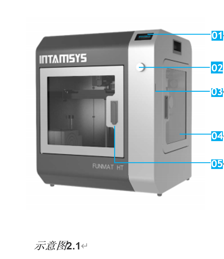
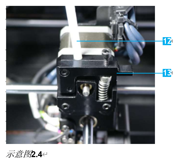
打印机总览
01. 操作触屏
02. 按压/旋转 按钮
03. SD卡插孔
04. 料箱
05. 前门
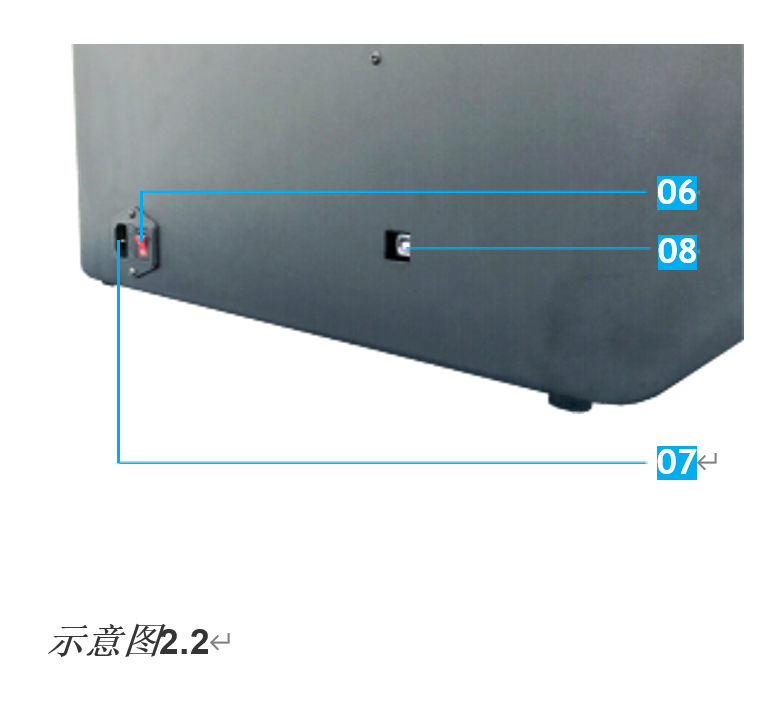
06. 电源开关
07. 电源插座
08. USB 插口
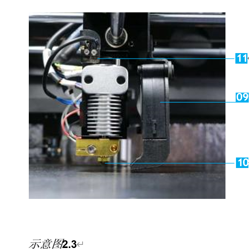
09. 冷却风扇
10. 喷嘴
11. 自动调平传感器
12. 导料管
13. 压紧螺钉—控制进给齿轮松紧
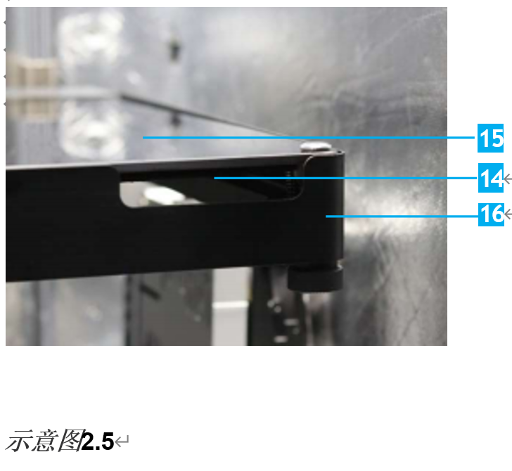
14. 热床 (玻璃板下方)
15. 玻璃板
16. 玻璃板保持架
¶ 打印机参数
打印机参数
| 产品 | FUNMAT HT |
| 打印技术 | FFF |
| 喷头 | 单个 |
| 喷头直径 | 可交换 0.25, 0.4,0.6 和 0.8mm 喷嘴, 默认 0.4mm |
| 每层精度 | 0.05-0.4mm |
| 轴向精度 | XY:0.025mm, Z:0.0025mm |
| 打印速度 | 30-200mm/s |
| 打印丝直径 | 1.75mm |
| 打印平台 | PI + 微晶玻璃 |
| 可用材料 | PEEK, PEKK, PEI, PPSU, ABS, PC, Nylon, Carbon Fiber-Filled, PETG, PVA, PLA, TPU, HIPS, 木料填充, 金属填充, etc. |
| 操作语言 | 中文 & 英文 |
| 用户界面 | 全彩触摸屏 |
| 数据联通 | SD卡, USB |
| 监控摄像头 | 有 |
| 断电恢复 | 有 |
| 缺丝警告 | 有 |
| 打印平台调平 | 自动调平, 手动调平 |
| 打印体积 | 10.3"*10.3"*10.3"(260*260*260mm) |
| 整机尺寸 | 530*490*645mm |
| 重量 | 58kg |
| 热床温度(MAX) | 160°C/320°F |
| 挤出机温度(MAX) | 450°C/842°F |
| 腔室温度(MAX) | 90°C/194°F |
| 软件 |
INTAM-Suite(自开发的免费3D打印机切片软件); 可兼容软件: Simplify3D & Cura |
| 输入模型的格式 | .Stl, .Obj, .X3D |
| 输出模型的格式 | .Gcode |
| 操作环境 | 温度: 15°C To 32°C (59°FTo 89.6°F) 湿度: 30% To 70% |
| 贮存环境 |
温度: 0°C To 54°C (32°F To 129.2°F) 湿度: 10% To 85% |
| 材料贮存环境 |
温度: 13°C to 24°C (55.4°F To 75.2°F)湿度: 20% To 50% |
| 输入电压 |
100~120VAC (仅110V版本,参考铭牌) 200~240VAC (仅220V版本,参考铭牌) 47~63Hz |
| 功率 | 1200W |
¶ 03 入门
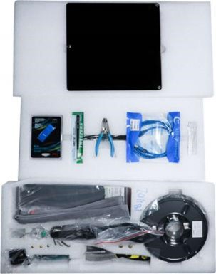
¶ 配件清单
配件清单
配件盘包含您在使用 FUNMAT HT 3D 打印机时需要的所有配件。以下是配件清单列表,包含在您的机器中。
| 电源线 | SD卡和电子文件 | 读卡器 |
| USB数据线 | 剪钳 | 镊子 |
| 移除工具 | 玻璃板 | 玻璃板组件 |
| 喷头组件 | 耗材 | 六角扳手 |
| 内六角扳手 | 扳手 | 调平卡 |
| 手套 | 进给齿轮 | 喷嘴 |
| 驱动马达 | PEEK管 | 扎带 |
| 快速指南 | 监控指南 |
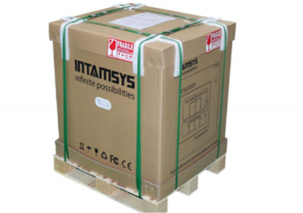
¶ 拆开打印机外包装
打印机拆包
拆开包装前,请将打印机置于平坦的地面。
步骤 1: 打开箱子。
步骤 2:移开配件托盘,并从箱中拿出机器。

步骤 3: 将打印机轻放至平整、坚固的平面上
并接插电源线,启动打印机
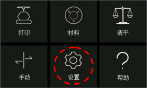
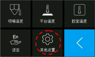
步骤 4: 点击触屏,按以下操作降低打印平台高度 “设置”⇢“其他设置”
⇢“平台降低至 底部”。打开前门, 轻轻移开打印平台上的塑料泡沫固定
架,关闭打印机电源。

请保留所有包装材料以备保修之用。
¶ 设置打印机
设置打印机
¶ 解除打印机头限制
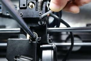
打开打印机天窗, 可见打印喷头被四个螺钉限制了移动方向。在您使用打印机前,应解放X&Y轴的移动限制。
按如下操作进行:
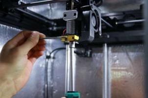
步骤 1:关闭打印机电源。请使用六角扳手和内六角 扳手来移除限制
机器X、Y轴向移动的四个螺钉。
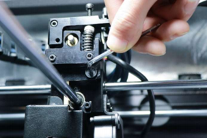
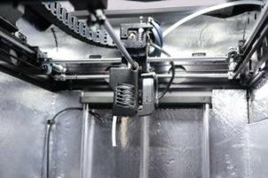
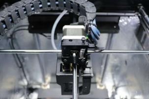
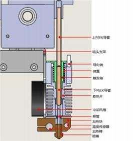
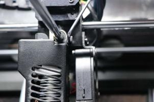
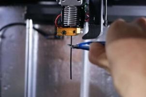
步骤 2:将马达安装在挤出机上方,并确保中间的PEEK 管安插牢固。
将马达连接器连接在转接板的P7位置。电缆用电缆扎带固定。
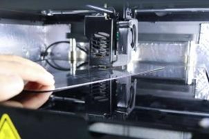
¶ 设置打印平台
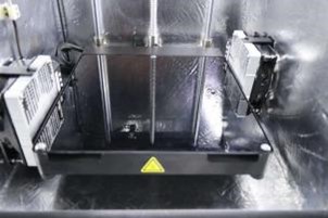
在配件托盘中找到玻璃板组件的位置。将玻璃板 组件取出, 并放置在如图所示
的平台上。将三个玻璃板上的三个磁铁与平台上的磁铁保持架对齐。
¶ 启动电源
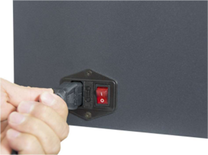
步骤 1:连接电源电线。

步骤 2:将电源开关拨至开(I)位置。
打印机启动。触屏启动, INTAMSYS的标识
也会随启动代码短时间显示。
¶ 04 LCD 显示屏
LCD显示屏
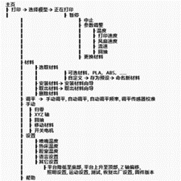
主菜单如示意图4.1树形展开。
介绍
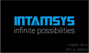
这是启动机器时显示屏的画面。
启动画面包括:
a) Intamsys 标识;
b)屏幕固件版本,例如 “LCD3P2 V2.0”;
c)机器固件版本“HT1.5_ 190313”
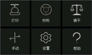
主界面
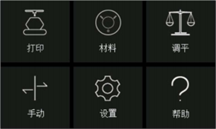
主界面紧接着启动画面显示,如右图。在主界面上, 分为六个
部分 – (a)打印 (b)材料 (c) 调平 (d) 手动(e) 设置 (f)帮助。
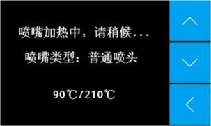
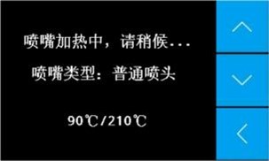
打印界面
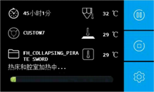
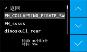
选择“打印”选项,您将会被询问想要打印的模型 文件。一旦您选择了
将要打印的文件,界面就如右 图显示。在这个界面将会展示喷嘴、
打印平台和腔室的温度,还有所用材料类型,打印所需时间和打
印过程。
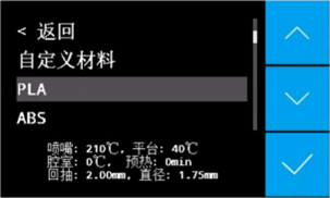
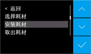
材料界面
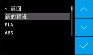
在这个界面,您可以在预设的耗材列表中选择希 望使用的材料。
如果您的耗材材质没有在该列表 中列出,您也可以自行添加一种
新的材质, 并通 过“自定义”选项设置其属性。您也可以在“材
料”界面中安装或取出耗材。
打印平台

在此有四个子菜单。 A)手动调平, B)自动调平, C)自动调平频率,
D)调平传感器校准。用户可以 选择手动调平通过人工操作调平打印
平台,调平 过程可以根据显示屏上的指示进行。自动调平更 易使
用, 点击这个菜单打印机将会自动探测打印 平台位置。调平传感
器校准功能将会帮助校准喷嘴与调平传感器间的距离。
手动
在这个界面,您可以执行运动轴任务,如归零位、
沿XY方向移动喷嘴机构,或者修改回抽设置。
设置
在这个界面,您可以修改喷嘴温度、打印平台温度或
腔室温度。您也可以修改操作语言, 或其他参数。
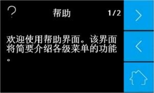
帮助
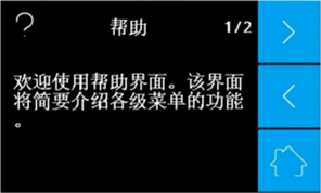
在这个界面,您可以在显示屏上找到各种操作图
标及其功能的简介。
¶ 05 常规操作
¶ 打印平台调平
打印平台调平是成功打印模型的先决条件。此操
作的目的是明确打印平台的平整性,及其与喷嘴之间的
精确距离。为了调整喷嘴与打印平台间的间隙在约
0.2mm左右(大概是一个标准调平卡的厚度) ,您
只需使用调平卡或调平设备来进行一些简单的人
工调整。
打印机也提供自动调平功能,原理是在打印时探测三点位置, 按算法自动调整喷嘴
与平台间间距。
注意:在调平前请确认所有机器零件都正确安装, (比如没有松动的零件)打印平台上下也没有异物。
¶ 手动调平
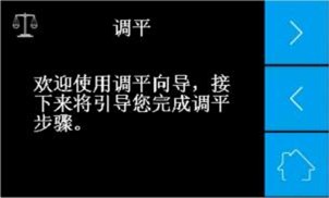
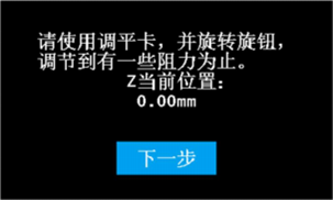
步骤 1:将调平卡从配件盘中取出。如果您不慎弄
丢了调平卡,也可以使用两张标准A4纸
(~0.2mm)。进入机器主界面,并依次点击 “调平”
“手动调平”,根据屏幕提示,完成调平操作。
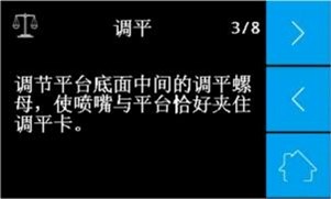
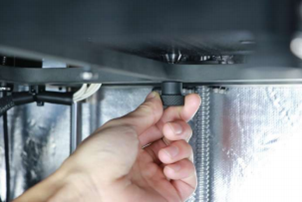
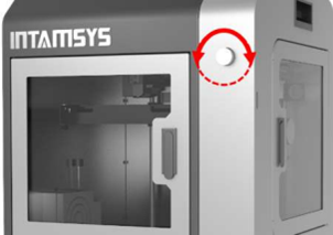
步骤 2:打印平台下方有旋转螺钉。其中一个是在 背面中心处,
一个在左前处,另一个在右 前处。当您开始调平平台时,机器会
自动 将喷嘴移至需要调整的螺钉上方。从中间 的螺钉开始,按顺
时针方向旋转可以减少 喷嘴与平台的间距,逆时针旋转则是增加 间
距。喷嘴与打印平台的间距按以下方式 最为合适: 当您在喷嘴
与平台间滑动调平卡(随机器装运)时,可以感到稍许摩擦
阻力。

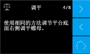
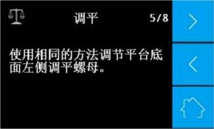
步骤 3:重复此过程调整平台下方的左和右螺钉。
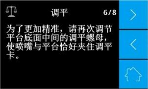
步骤 4:为了调平更加精确,需要多次进行手动
调平, 在调平完成后, 就可以准备安装耗材了。
注意:
1) 如果您选择了手动调平选项。在打印需要腔室加热的材质前(如PC、ABS 等),请先将腔室 温度加热至打印时所需的温度,并在调平前保温至少30分钟。在调平打印平台前预热腔室非常重要,因为在腔室加热时打印平台可能会上升。
2) 如果打印时耗材没有挤出或者挤出后不能粘附到玻璃板上,可以调整打印平台下的三个螺钉直至耗材挤出顺畅或挤出后可以粘附到玻璃板上为止。
¶ 自动调平
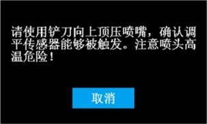
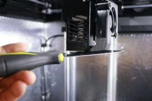
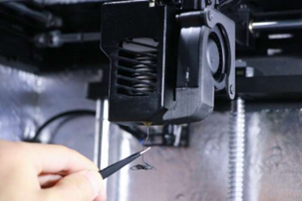
步骤 1:检查调平传感器是否正常。返回触屏主
界面, 点击“设置”⇒“其他设置”⇒“测试”
“调平传感器”。此 时喷嘴将被加热。等候大约两分钟,再 根据
显示屏上的指示,使用铲刀触碰加 热后的喷嘴,将其向上抬约1mm。
显示 屏提示消息“调平传感器已被触发,测试通过”。
注意: 如果调平传感器不能正常工作,请一 定不要使用自动调平
功能,否则喷嘴将会损坏玻璃板!

注意: 此步骤并不是每次都必要,如果您更 换了喷嘴组件、调平传感器
或者插线 电缆,那么此步骤才是必要的。我们 也建议您在每月都进行
一次调平传感器测试。
步骤 2: 返回触屏主界面,点击“调
平”⇒“调平传感器校准”。 根据指 示完成校准工作。喷嘴的加热温度取决
于所选材质。

注意:此步骤并不是每次都要求,如果您更 换了喷嘴组件或者
调平传感器,此步骤才必 要。如果您打印的3D模型不能很好
的粘附在 玻璃板上,请在自动调平功能前,重做此步骤。

步骤 3: 点击“自动调平”, 打印机将会自动完成 自动调平程序,
不需要任何人工干预。首 先,机器将预热打印平台和腔室,然后预
热喷嘴。加热温度依据耗材材质决定。一 旦到达设定的温度,打印
机将开始自动调 平。一旦自动调平完成,显示屏将会提示 “自动调平成功!
”此时打印机已准备好开始打印工作。


注意:如果打印时耗材没有挤出或者挤出物没有粘附在玻璃板上,请重复步骤2、3.
¶ 选择耗材
选择耗材
您可以通过两种方式选择您想要打印的耗材。
1) 直接在默认的材料列表中选择, 比如PLA、ABS、
PC等,设置将在屏幕底部显示。
2) 更新材料设置或命名一种新的材料。
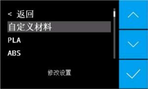
步骤 1:在材料列表的顶部点击“自定义材料”,
修改设置参数,如喷嘴温度、热床温度、
腔室温度、预热时间、耗材直径、材料流 速、回抽长度、
回抽速度、维持热床温度、维持腔室温度、维持时间等。
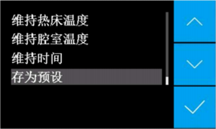
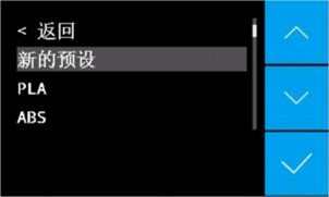
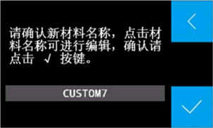
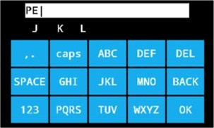
步骤 2:点击“存为预设”,您可以通过点击列表
中的材料重写材料设置,或者点击“新预
设”编辑新的材料,也可以命名这种新材
料并保存。
¶ 安装耗材
安装耗材
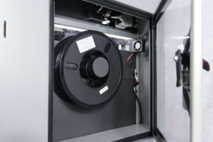
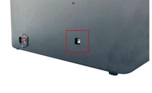
步骤 1:打开机器右侧的侧门,将耗材丝盘放置
在保持架上。
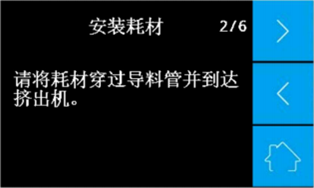
步骤 2:在丝盘末端取出打印丝,通过缺丝报警开
关进入导料管,到达挤出机。
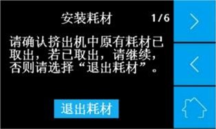
步骤 3:点击“材料”,选择希望安装的耗材材
质,然后点击“安装耗材”。
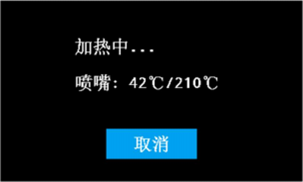
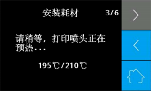
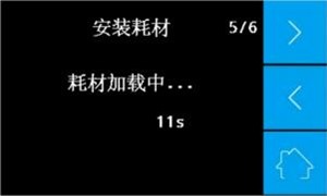
步骤 4:参考显示屏上的指示操作,并等待喷嘴
温度上升到所需温度。
步骤 5: 点击“材料”,选择希望安装的耗材,然
后点击“安装耗材”。

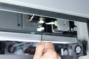
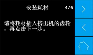
步骤 6:从挤出机中拉出导料管,将耗材插入进给 齿轮中。当
耗材进入进给齿轮后,将导料 管插回进料口,并按照显示屏指示的下一
步骤继续操作。
步骤 7:根据屏幕上的计时器,等候耗材丝从喷
嘴中顺畅挤出。此时耗材安装完毕。


警告:
在耗材挤出过程中,喷嘴温度极高。注意在安装过程中不要触碰喷嘴。
¶ 打印工件
打印工件
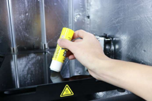
步骤 1:在打印平台上涂好PVP胶水。

步骤 2:将您希望打印的3D模型文件保存入SD卡中, 并插入机器。
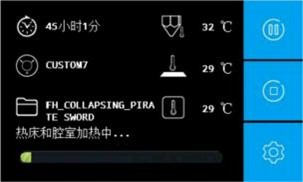
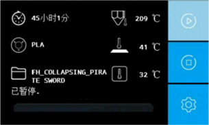
点击“打印”,选择您希望 打印的模型文件。等候机器加热至所需温
度。打印过程中的显示屏画面如图所示。打印所需时间、选用材料、
喷嘴温度、热 床温度、腔室温度都会被展示在屏幕上。 您可以通过
点击图标中止打印、暂停打印和修改设置进行相应操作。
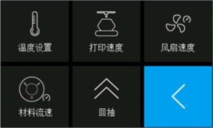
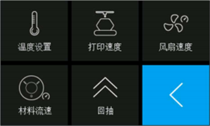
步骤 3:如果您选择修改设置,显示屏将如图所示。 在此可以
更改温度、打印速度、风扇速度、材料流速和回抽设置。
¶ 更换耗材
更换耗材
¶ 打印中更换耗材
步骤 1:在显示屏上点击暂停。
步骤 2:当喷嘴停止后,点击设置并选择“更换材料”
根据指示取出导管和耗材。
步骤 3:安装新的耗材时,应将耗材丝直接插入进给 齿轮沟槽中,
并通过手力将一小段耗材推入 挤出机中。同时,确保温度设置已更改至适
合新材质的参数。
步骤 4:点击继续按钮,恢复打印工件。
注意:为避免堵塞喷嘴,请不要将耗材更换为熔点更低的材质。
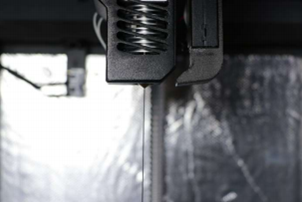
¶ 缺丝时更换材料
此款打印机具有缺丝报警功能,当耗材用完时机器会暂停并提示警告。在置换新的耗材后,打印机将会继续执行打印工作。
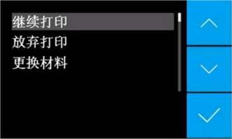
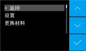
步骤 1:缺丝时,屏幕将会如右图所示。点击“更
换材料”,按随后指示操作取出耗材,并
拿出耗材料想中的打印丝盘。然后安装新
的丝盘,并按步骤安装新耗材。
步骤 2:在新耗材安装好后,点击“继续”按钮恢
复打印工作。
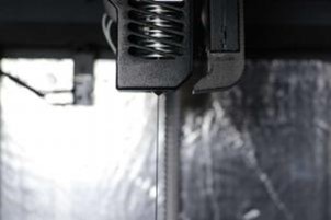
¶ 打印完成后更换材料
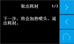
步骤 1:如果您想更换新的材料,请点击“材料”,
再点击“取出材料”。
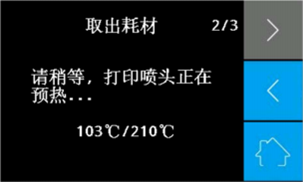
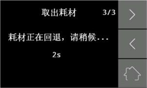
步骤 2:参考显示屏指示,并等待喷嘴升至所需温度。
等候旧的耗材从挤出机中反转出来。

步骤 3:安装新材料。点击“材料”⇒“安装耗材”。
如果您希望更换耗材,请先点击“选择耗材”, 再安装耗材。
请参阅本手册安装耗材章节,了解更多关于如何安装耗材的内容。
注意:为避免堵塞喷嘴,请不要将材料更换为熔点更低的材质
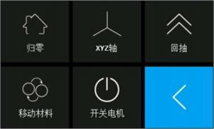
¶ 其他功能
其他功能
XYZ轴运动
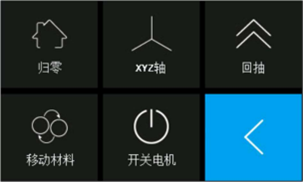
XYZ轴部分是用于手动使用电机调整X、Y &Z轴坐
标。
归零

使用此命令使X、Y &Z轴回到归零位置。
XYZ

此功能用于手动改变X、Y & Z坐标。您可以通过点 击按钮或
使用旋钮移动喷嘴、调节平台至期望的位置。
回抽
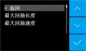
此选项用于设置最大回抽长度和最大回抽速度。
回抽功能主要用于在喷嘴移动时回拉耗材。
移动材料
此功能用于挤出机上下移动耗材。
开关电机

点击“开关电机”关闭步进电机电源。
设置

在设置部分,可以更改喷嘴温度、热床温度和腔
室温度,也可以更改语言设置和其他参数。
喷嘴温度
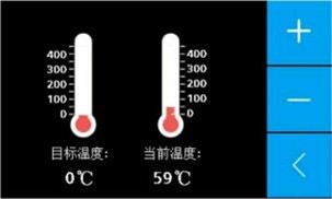
提升或降低喷嘴温度。在该选项中,可以观察到 目标温度和
实际温度。也可以在此处修改目标温度,长按(+) / (-)或使用旋钮更改。
热床温度
提升或降低热床温度。在该选项中,可以观察到 目标温度和实际温度。
也可以在此处修改目标温度,长按(+) / (-)或使用旋钮更改。
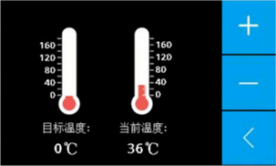
腔室温度

提升或降低腔室温度。在该选项中,可以观察 到目标温度和实际温度。
也可以在此处修改目标温度,长按(+) / (-)或使用旋钮更改。
语言

更改语言设置。
其他设置

更改一些其他参数。
帮助部分
这个部分提供一些很有用的信息。
¶ 更换喷嘴组件
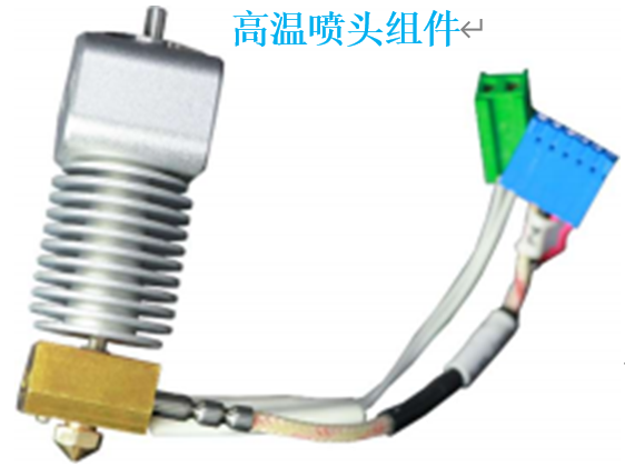
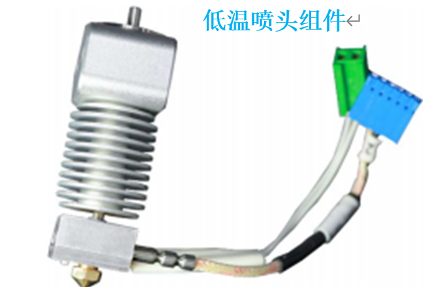
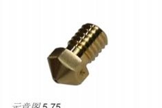
随打印机将会发运两款喷嘴组件。 一款已经装在 打印机中,是低温喷嘴。
它是用于打印PLA、ABS、 PC和其它熔点低于270 ℃的材料。另一款的最高
温度是450℃, 用于打印高温材料, 例如PEEK、
Ultem和PPSU(喷嘴组件有短线在适配器中)。
步骤 1:为了更换喷嘴组件,首先,需要将喷嘴中的 材料全部移除。
如果耗材卡在喷嘴中,可以手动提升喷嘴温度,再将其拉出来。
步骤 2:关闭机器电源,并让喷嘴冷却至室温。注意
高温喷嘴!
步骤 3:使用螺丝刀取下喷头组件盖板和组件上的固
定螺钉。

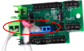
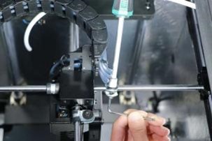
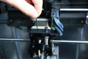
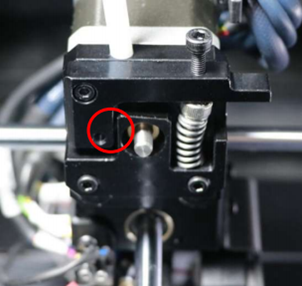
步骤 4:拔掉喷头组件后面的接插件(图中已圈出)。
在拔出时注意捏紧接插件上的搭扣。

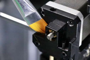
步骤 5:更换新的喷头组件,确保PEEK管插牢,
并且微型开关恰好触到喷头组件的上
表面。将6针连接器插入针插板的P4,
将2针连接器插入针插板的P2。
步骤 6:将步骤3中取出的螺钉再安装回原位。
步骤 7:检查调平传感器功能,请遵照“自动
调平”章节的步骤1进行。如果调平传
感器不能被触发或者喷嘴组件没有提
升时就触发,请重复步骤5。
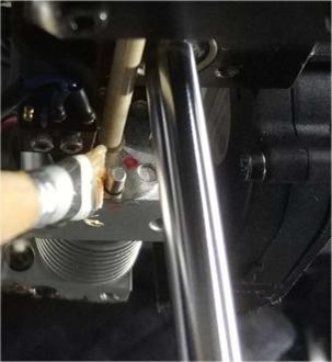
¶ 只换喷嘴
只换喷嘴
如果您只想更换喷嘴,请参考以下步骤进行。
步骤 1:在更换喷嘴前,应先将喷嘴中所有耗材清除。
步骤 2:使用螺丝刀将喷头组件盖板上的螺钉取出。
步骤 3:点击“移动材料”,将耗材加热至熔点温度。 然后使用扳手固
定住加热板,再用内六角扳手将旧的喷嘴取出。
步骤 4:推出残余耗材,将其剪断。然后回抽至喷 嘴。
注意:如果不小心将Teflon管掉出,请将其重新推回。
步骤 5:安装新的喷嘴,并重装喷头组件盖板及螺钉。
¶ 取出模型 & 清除支撑
当 3D打印工件完成后,必须及时将其从玻璃板上移除,此时工件仍维持于显示屏中所示温度。在打印 工件冷却后再移除工件可能造成玻璃板损坏,因为工件的冷却收缩速度大于玻璃板。打印机对于每种材料都有“维持热床温度”的预设值,该预设值保证打印工件在打印完成后仍可保温。取出玻璃并尽快取走打印工件。同时,也要当心受热的元件,如腔室、平台和喷嘴。使用与打印机随运 的铲刀将模型取出。注意不要损坏玻璃板。根据切片时的设置,可能需要移除模型上的沿边、底座或支撑。 使用我们提供的剪钳和镊子可以完成这项工作。如果您对模型的表面质量或工件外观有特殊要求,可以使用金属锉刀和砂纸进行光滑打磨。
¶ 06 维护
¶ 升级固件
INTAMSYS会定期发布新版本的固件。我们建议定期升级固件来保持INTAMSYS FUNMAT HT 拥有最
新功能。升级可以通过USB端口在FUNMAT HT机器上实现。
步骤 1:可以在https://www.intamsys.com网站
或联系info@intamsys.com邮箱下载最新的固
件文件。
步骤 2:将firmware .hex文件存入电脑中。
步骤 3:使用USB数据线连接电脑和打印机。
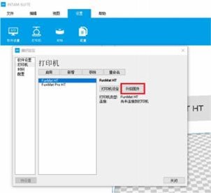
步骤 4:打开INTAMSUITE切片软件,进入设置->
打印机->升级固件。
步骤 5:选择用于升级的固件文件。
步骤 6:升级完成后,请谨记恢复出厂设置, 点
击“设置->其他设置->恢复出厂设置”。
¶ 清理玻璃板
打印过后,原来在玻璃板支撑打印工件的胶水将 会在平台上逐渐聚集。这将会引起平台表面的不 平整,对随后的打印工作造成负面影响。所以,玻璃板需要定期清理。
下面将会介绍清理玻璃板的步骤。
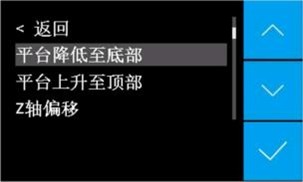
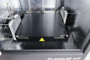
步骤 1:降低打印平台,点击“设置”⇒“其他设置”⇒“平台降低至底部”。

步骤2: 取出玻璃板。
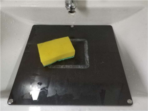
步骤 3: 用清水冲洗玻璃板,再用布擦干。如果
需要也可使用海绵或肥皂。
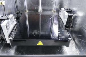
步骤 4:将玻璃板放置在平台上。玻璃板上的三
个磁铁与平台上的磁铁保持架对齐。
¶ 清理进给装置
多次打印后,一些塑料微粒会渐渐聚集在进给装 置的齿轮中。这些微粒可以
通过吹风或者简单的 刷子清理。如果发现耗材经过进给装置被磨损, 我们建议
您需要清理进给装置。压紧弹簧在完全拧紧螺钉后可以稍微拧松一点,这样压
杆就可以自如伸展。
¶ 清理喷嘴
在使用FUNMAT HT 3D 打印机时,喷嘴可能被一些
脏材料粘住。这些材料并不损害打印机,但我们仍
然建议保持喷嘴清洁,这样才可以得到最好的打
印效果。
清除喷嘴外的残料可按以下步骤进行。
步骤 1:将喷嘴加热至耗材熔点温度,使外部的 材质可以变软。
可以通过“设置”⇒“喷 嘴温度”,通过(+) /(-)按钮或旋钮改变目
标温度,实现喷嘴加热
步骤 2:喷嘴处于加热热状态时,使用镊子清理材料
时请注意安全。

警告:千万不要触碰发热的喷嘴,在清理时也请格外注意。
¶ 润滑导轨
如果打印工件表面出现小凸起或者发现X Y Z 导轨出现干摩擦,这意味着
需要润滑X Y Z 轴导轨了。这有助于保持打印机良好运行。
通常, 我们建议在执行200-300小时打印工作后, 或一周后(有腔室) ,
或两周后(无腔室) ,需要润滑X Y Z轴导轨。
因物流原因,我们无法随机器运送润滑脂。所以, 我们推荐您自行购
买一些机器润滑脂,可以使用全氟聚醚润滑脂进行润滑保养
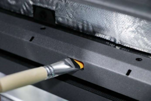
¶ 润滑导向销
如果在执行“调平传感器校准”测试时(“自动 调平”章节步骤1中提到),
需要使用很大力气 才可以触发自动调平传感器,那意味着需要润滑 导向销了。
这有助于保证自动调平功能的精度。通常,我们建议每月润滑一次导向销。
因物流原因,我们无法随机器运送润滑脂。所 以,我们推荐您自行购买一些
机器润滑脂,可以使用全氟聚醚润滑脂进行润滑保养。
¶ 保护耗材
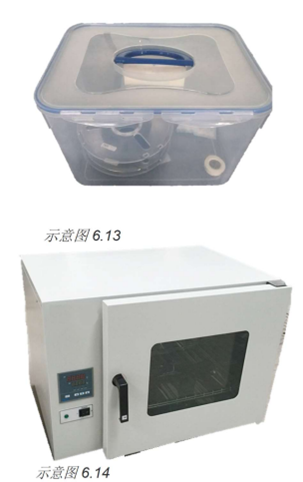
所有耗材对水汽高度敏感。我们强烈推荐将耗材 保存在有干燥剂的
密封容器或袋子中。打印时也推荐使用干燥盒。
如果耗材粘有水汽,将会造成诸多不良结果,如 发泡、拉丝、
未挤出或者粗糙面。如果残余水汽很多,可以使用对流烘箱干燥耗材。
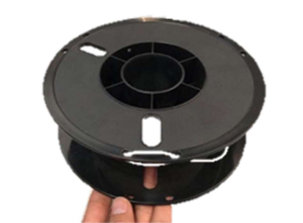
取出耗材后,将其穿过丝盘一侧的小洞,可以防
止耗材丝乱丝。请确保耗材在打印前没有乱丝。
¶ 07 常见问题处理
注意:我们参考www.3dverstan.se作为本章内容,仅针对不同FDM 3D打印机上存在的常见问题。
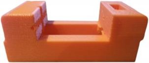
弯曲
弯曲主要常见于ABS材质。弯曲发生于材料冷却和收缩
过程中。当打印冷却下来并且轻微收缩,材料即开始
自我收缩。 最终,应力集中致使打印工件在平台弯曲。
解决弯曲的最佳方法就是加热打印平台。另一种解决方法是
在打印平台上涂胶提升粘接性。还有一种选择是在打印时
使用沿边/底座/裙边功能。这些功能在CURA软件中有。
偏斜
当喷头因摩擦导致其移动距离比预期要短时,通常产 生偏斜。
为防止偏斜,确保打印机的移动元件不会与打印机主体发生擦碰。
错层
如果打印机突然错层打印, 很可能是因为一个或多个
滑轮没有在轴上固定好。拧紧固定滑轮的紧定螺钉。
另一个原因可能是喷头被卡。注入2机油解决这个问题。
最后,检查导轨轴是否排齐。如果没有,请将导轨轴
按正方形排列。
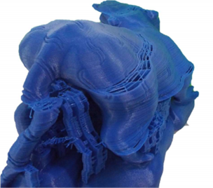
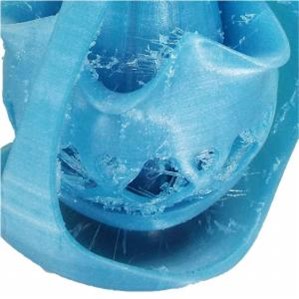
起球
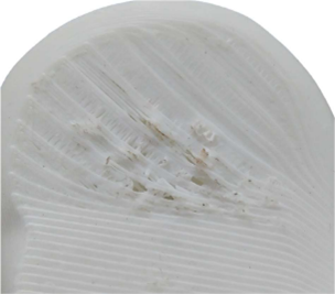
起球是打印工件上表面上出现的或开或合的凸点。如 果出现起球,
最重要的事情是确认冷却风扇在打印顶 层时正已最大速度工作。
如果冷却不到位,很细的热丝将会 卷曲并依附在工件表面,并使后续的
打印层很难正确地跨越工件模型间隙。另一种解决方法是打印更多的顶层和底层,
尤其是当打印层高很小时。
不圆/线条不相接
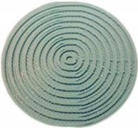
在打印圆形模型时,很可能结果并不理想。这个问题
是源于打印件的侧隙造成,而侧隙本身由于皮带松弛
引起。想要解决这个问题需要将皮带绑紧。先解开步进
马达限制, 向上或向下拉动以拧紧皮带,最后固定步
进马达的螺钉。
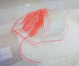
拉丝
拉丝是很细的不需要的耗材丝,它连接着打印工
件的各部位。解决拉丝的主要手段是回抽。设定回抽,
同时增加回抽长度可以防止塑料在喷嘴移动时渗
漏出来。另一种方式是加快打印速度,这相当于减
少了塑料渗漏的时间。第三种方式是降低打印温度。
但是降低打印温度也需要配合相应缓慢的打印速度,
才能防止材料挤出不足。
首层不粘/打印涣散
造成这种现象最普遍的原因是打印平台没有调平。调平打 印平台非常重要,
这关系到打印头的移动和喷嘴与平台的距离是否尽可能的完美。
磨损
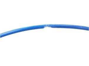
磨损发生于齿轮将耗材推送穿过喷嘴时,但是基于多
种因素,齿轮可能在耗材上打滑并且磨损耗材。耗材
被磨损的越多,就越难被推送,最终耗材不能被推进
或拉出。一种影响因素是挤出速度太快。尝试将挤出速
度降低至50% 。另一种解决方法是将喷嘴温度提高5-10℃。
最后,您可以尝试降低打印速度解决这个问题。
乱丝
乱丝可能导致各种打印问题。确保耗材缠绕完好。
进给压力
挤出时施加在耗材上的压力是可调的。这个压力应该
被调节到恰好没有磨损到耗材的最佳程度。调节压紧
螺钉的松紧可以调整进给压力。
欠挤出
欠挤出是打印机不能提供足额的材料流量。此问题可造 成缺层、
细层或者层间麻点、孔洞。如果您现在刚好有 欠挤出的问题,
请先确认您使用的耗材直径是否和喷嘴
直径相匹配。如果匹配,您可以尝试增加5%的材料流速。
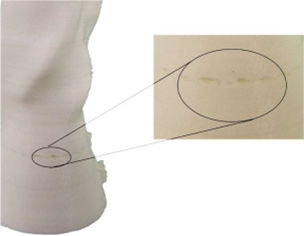
分层和滑层
造成分层和滑层的一个主要原因是层间高度太高。根据经
验,层高最大应是喷嘴直径的80%,例如当您使用0.40
mm 的喷嘴时,层高不应超过0.32 mm 。另一个造成分 层和滑层
的原因是打印温度太低。热塑料的粘接性通常 比冷塑料好很多,
所以提高喷嘴温度可能可以解决分层滑层问题。
喷嘴堵塞
如果材料不能从喷嘴中流出,其中一个主要的可能是
因为喷嘴被堵塞了。这是因为打印时喷嘴温度比材料
熔点高太多或低太多。如果喷嘴温度太高,耗材会被
碳化,造成喷嘴堵塞。如果打印温度太低,耗材没有
得到足够的融化,将不能从喷嘴中挤出。另一个造成
堵塞的原因是喷嘴与平台间的距离。如果距离太近,
耗材将被阻挡,不能从喷嘴中挤出。在这种情况下,
应该重新调平打印平台。
¶ 08 软件
INTAM-suite是基于Cura开发的切片软件。为了使工件模型可以被3D打印机识别,首先您需要使用一款 切片软件将STL模型文件转换为GCode 格式。完成GCode格式转换,就可以将文件加载入打印机开始打
印。
¶ 下载并安装软件
步骤 1:可以在随打印机一起的SD卡中下载软件。也可
以在我们的网站中下载:
www.INTAMSYS.com
按照教程完成安装。
步骤 2:双击SD卡中的软件图标。

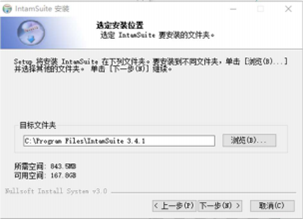
步骤 3:选择想要安装INTAMSUITE的目标文件夹,并点
击"Next"。
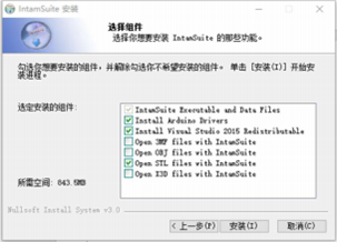
步骤 4:选择所有希望安装的功能,然后点击“安装”。
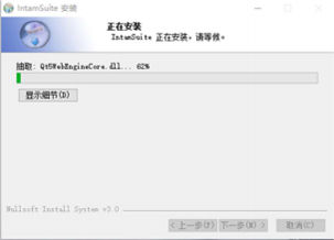
步骤 5:等待程序安装一段时间。
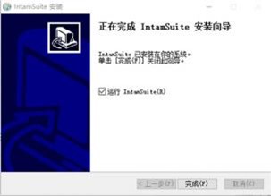
步骤 6: INTAM-suite 安装完成!
步骤7: 点击“完成
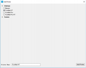
步骤 :8:选择打印机型号,点击“添加打印机”,就
可以使用相应机器型号的INTAM-suite了!
¶ 工作界面概述

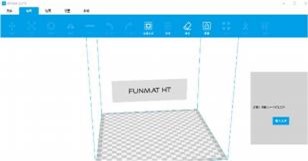
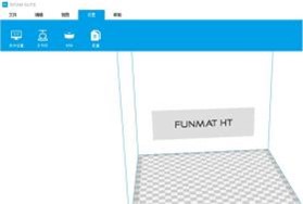
文件界面
在这个界面可以执行打开文件、保存G-Code等常规 操作。
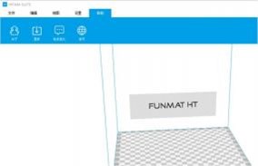
编辑界面
模型界面
设置界面
帮助界面

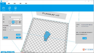
¶ 软件使用
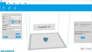
步骤 1:加载STL模型。
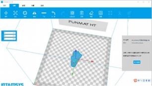
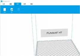
步骤 2:编辑STL模型。
确保工件平放在平台上。此时可以使用旋转、 缩放和镜像功能修改工件模型,
他们在界面左 上角。视角功能在右上角。可以调整视角模式
得到最佳观察位置。
步骤 3:打印STL。
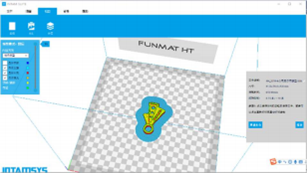
在完成文件修改后, 就可以依照需求设置打印。 快速打印提供了相对低
的打印质量,但需要更 少的打印时间。正常打印和高质量打印,对应更
高 的打印质量和更低的打印速度。也可以选择特定 类型的材料、喷嘴
直径、支撑类型和平台粘附类型。
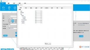
如果想自定义打印设置,或对于打印条件有特殊的要 求,可以点击“完整设置”
进入专业菜单的完整设置功能。在这个页面,可以自主修改每一项打印设置。
如果您是专业的3d 打印机使用者,这里有更多的设置
功能可供进行专家级使用。
步骤 4:保存为G-Code文件。
¶ 09 术语
| Terminology | Definition |
| Numerical | |
| 3Doodler | A kind of 3D Pen that can be used to draw three-dimensional objects. |
| 3D Bioplotter | Well reputed 3D Bio-Printing machine from Envision-tec. |
|
3D Bio-Printing |
The process of creating cell patterns in a confined space using 3D printing technologies, where cell function and viability are preserved within the printed construct. |
|
3D Model |
A three-dimensional design usually produced using various 3D modeling software’s like CATIA, CREO, SOLIDWORKS. |
|
3D Printing |
Process of creating a three-dimensional object by depositing material layer by layer. |
| 3D Sand Casting | A metal casting process characterized by using sand as the mold material. |
|
3D Scan |
A process by which the shape and texture of a real world object is captured and displayed as a 3DModel. |
|
3D Systems |
Well known 3D Printing companyfounded by the inventor of 3D Printing technology. |
| A | |
|
ABS: Acrylonitrile Butadiene styrene |
A popular thermoplastic material heavily used in 3D Printing. |
|
ABS Glue |
Made by adding a bit of acetone to the ABS filament. This is used to stick the 3D Print to the buildplate. |
|
Acetone |
An organic solvent used to dissolve left over filament in a nozzle to unclog the nozzle and also for smoothing the ABS printedobject surface. |
|
Additive Manufacturing |
Process of creating a three-dimensional object by depositing material layer by layer. |
| All Metal Hot End | A nozzle design that can go up to temperatures of 400℃ . |
|
Alumide |
A material used in 3D printing consisting of nylon filled with aluminum dust. Its name is a combination of the words aluminumand polyamide. The printedobjects have a metallic look. |
| Terminology | Definition |
|
AMF |
Additive Manufacturing File Format is an open standardfor describing objects for additive manufacturing processes such as 3Dprinting. |
| Amorphous | Without a clearly defined shape or form. |
| Anisotropic | Object with physical properties that are different in different directions. |
| B | |
| Bed | Platform on which material gets extruded. |
|
Binder Jetting |
A 3D Printing process where binder is jetted after each layer to glue it to thenext layer. |
|
Biopolymer |
Polymers produced by living organisms. Since they are polymers, biopolymers contain monomeric units that are covalently bondedto form largerstructures. |
| Blender | An open source3D modeling software. |
|
Bridges |
Printing horizontal layers in the air without support. To achieve good quality for bridges, it is recommend to reduce printing speed and printing temperature. |
|
Brim |
Attached to a model and extends outward. Brims typically have several outlines and may be a few layers tall. Brims are often used to stabilize small parts of a model, such as legs of a table, becausebrims help these areas stay connected to the print bed. |
| Build Plate | The platform on which material is deposited layer by layer. |
| Build Platform | Same as build plate. |
| Build Time | Time it takes to print the object as per the parameters defined in slicer software. |
| Build Volume | Build volume = Printer Length x Printer Width x Printer Height. |
|
Build TAK |
A sheet that is placed on the build plate before extruding the material to avoid warping of printed objects. |
| C | |
| CAD / CAM | Computer Aided Design / Computer Aided Machining. |
|
CAE |
Computer-aided engineering is the broad usage of computer software to aid inengineering analysis tasks like Finite Element Analysis. |
| Terminology | Definition |
| Catia | Popular 3D Modeling software. |
|
CJP : Color-Jet-Printing |
A type of 3D Printing technology from 3D Systems, primarily for printing multi- color objects. |
| CLIP | Continuous Liquid Interface Production. |
|
CNC Machining |
A process used in the manufacturing sector that involves the use of computers to control machine tools. |
|
Crystalline |
A crystal or crystalline solid is a solid material whose constituents are arranged in a highly ordered macroscopic structure, forming a crystal lattice that extends in alldirections. |
| Curing | A process of hardening photopolymers through UV light. |
| D | |
|
DLP : Digital Light Processing |
A type of 3D Printing technology where photopolymers are cured using UV light. |
|
DMLS: Direct Metal Laser Sintering |
A type of 3D Printing technology. |
| E | |
|
EBM: Electron Beam Melting |
A type of 3D Printing technology which uses an electron beam instead of a laser or thermal printhead. EBM is often used for the production of incredibly dense metal parts. |
|
End Stop |
3D Printer axes all need a datum (also known as home position or end-stop) to referencetheir movements. |
| EOS | Industrial 3D Printing company well known for its metal 3D Printing. |
| Extruder | A device that sends a certain amount of filament to the hot end. |
| F | |
| FabLab | A small-scale workshop for digital fabrication. |
|
FDM: Fused Deposition Modeling |
A type of 3D Printing technology that uses heat to melt and extrude plastic filament ontothe build plate. |
| Filament | Plastic wires used in FDM 3D Printing. |
| Terminology | Definition |
|
Fixture |
Used to hold a workpiece during either a machining operation or some other industrial process. |
| Flowrate | The volume of fluid that passes per unit time. |
| G | |
|
G-Code |
The common name for the most widely used numerical control (NC) programming language. It is used mainly in computer-aided manufacturing to control automated machine tools. |
|
Glass Transition Temperature |
Glass Transition Temperature (Tg) is the temperature regionwhere the polymer transitions from a hard, glassy material to a soft, rubbery material. |
| H | |
| Hardening | Harden (make an object tougher) generally by using heat treatment. |
|
Heated Bed |
Heated build platform (also called heated bed) improves printing quality by helping to prevent warping. As extruded plastic cools, it shrinks slightly. Heated beds usually yieldhigher quality finished builds with materials such as ABS and PLA. |
|
Heated Build Chamber |
Heated build chamber also improves the printing quality by maintaining the constanttemperature in the chamber therebyavoiding cracks. |
| HIPS | High Impact Polystyrene is a type of 3D Printing filament. |
|
Hot End |
The device that melts the filament and extrudes the molten filament onto the build plate. |
|
Hydrogel |
A network of polymer chains that are hydrophilic. Hydrogels are highly absorbent naturalor synthetic polymeric networks. |
| I | |
| Infill | Material that is used to fill in gaps/holes. |
|
Injection Molding |
The plastic injection molding process produces large numbers of parts of high quality with great accuracy, very quickly. |
|
Inkjet Bioprinting |
The process of printing tissues through a jetting process similar to 2D Printing where a combination of hydrogel and cells are jetted into a scaffold as per a predetermined model. |
| Terminology | Definition |
|
Isotropic |
An object having a physical property which has the same value when measured in different directions. |
| J | |
|
Jig |
Used to hold and guide a workpiece during either a machining operationor some other industrial process. |
| K | |
|
Kapton Tape |
A kind oftape used to avoid product warping during the printing process, especially for ABS material. |
| L | |
|
Layer Height/Slice Thickness |
Height of each layer that gets deposited on the build plate. |
| Layer Thickness | Same as layer height/slice thickness. |
| Layout | The way in which the parts of something are arranged or laid out. |
|
LCF : Laser Cladding Forming |
A type of additive manufacturing technology. During the process of laser cladding forming, a high power laser beam is focused onto the substrate to create a molten pool.Metal powders are simultaneously injected into the focal zone by the powder delivering nozzles and then melted and rapidly solidified. |
|
LENS: Laser Engineered Net Shaping |
An additive manufacturing technology developed for fabricating metal parts directlyfrom CAD model using metal powder injected into a molten pool created by a focused, high-powered laser beam. |
| Linear Guide | Used for movement across an axis (X, Y, and Z). Meant for higher accuracy. |
| Linear Rail | Used for movement across an axis (X, Y, and Z). |
|
LOM: Laminated Object Machining |
An RP system where layers of adhesive-coated paper is used to build a 3D model. |
| M | |
| Melting Point | The temperature at which a given solid will melt. |
| Metal Powder | Generally used in Metal Laser Sintering. |
| Micron | A unit of measurement, 0.001 mm. Also known as a micrometer. |
| Terminology | Definition |
|
MJF: Multi-Jet-Fusion |
Proprietary 3D Printing technology developed by HP. |
|
MJP : Multi-Jet Printing |
Another term for Poly Jet Printing. |
| Monomer | A molecule that can be bonded to otheridentical molecules to form a polymer. |
| N | |
|
NEMA |
National Electrical Manufacturers Association offers standards for various products likeStepper Motors. |
| Nozzle | The metal tip where plastic material gets melted and extruded. |
| Nozzle Diameter | Diameter of the nozzle from where material gets extruded. |
|
NPJ: Nano Particle Jetting |
A metal inkjet 3D Printing process where nanoparticles suspend in liquid are jetted and later sintered. |
|
Nylon |
Kind of synthetic polymers that can be melt-processed into fibers, films or shapes. |
| O | |
| OBJ | A kind of 3D Printing file format. |
| Open SCAD | Software for creating solid 3D CAD objects. |
| Organovo | Calls itself a regenerative medicine company. |
|
Overhang |
A part of something that extends or hangs over something else. Supports are used to print overhangs. |
| P | |
|
PC |
Polycarbonates are a group of thermoplastic polymers containing carbonate groups in their chemical structures.Polycarbonates are used in engineering applications. |
|
PEEK |
Polyether etherketone (PEEK) is a colorless organic thermoplastic polymer in the polyaryletherketone (PAEK) family, used in engineering applications. |
|
PET |
Polyethylene terephthalate, commonly abbreviated PET is the most common thermoplastic polymer resin of the polyester family. |
| Photopolymerization | Process of changing the properties of photopolymer by exposing it to light. |
| Terminology | Definition |
|
PJP:Polyjet Printing |
PolyJet 3D Printing works similarly to inkjet printing, but instead of jetting drops of ink onto paper, PolyJet3D Printers jet layers of curable liquid photopolymer. |
| PLA | Polylactic Acid is a type of 3D Printing filament made out of corn starch. |
| PlasticJet Printing | Similar to FDM/FFF. |
|
Polyamide |
A synthetic polymer made by the linkage of an amino group of one molecule and a carboxylic acid group of another, including many synthetic fibers such as nylon. |
|
Polyphenylsulfone (PPSF) |
Polyphenylsulfone (PPSF or PPSU) is a type of high-performance polymer usually consisting of aromatic rings linked by sulfone (SO2) groups. |
| Post Processing | A set of processes used to smooth out the 3D Printed object. |
| PP : Plaster-based 3D printing | 3D Printing using sandstone or plaster as the input material. This is popular for creation of miniatures. |
|
PP : Polypropylene |
Polypropylene (PP), also known as polypropene, is a thermoplastic polymer used in a wide variety of applications including packaging and labeling. |
| Printing Resolution | Layer height in micrometers at which 3D Printing happens. |
| Printing Speed | The speed at which the hot end moves while extruding the filament. |
|
PTFE |
Polytetrafluoroethylene (PTFE) is a synthetic fluoropolymer of tetrafluoroethylene used for multiple applications. |
| PVA | Polyvinyl alcohol is a water-soluble synthetic polymer. |
| Q | |
| R | |
|
Raft |
A horizontal latticework of filament that is located underneath your part. Rafts are primarily used with ABS to help with bed adhesion. Rafts are also used to help stabilize models with small footprints, or to create a strong foundation on which to build the upper layers of your part. |
| RAMPS | RepRap Arduino Mega Pololu Shield. |
|
Rapid Prototyping |
A set of techniques used to quickly fabricate a scale model of a physical part or assembly using three-dimensional computer aided design (CAD)data. |
| Terminology | Definition |
|
RepRap |
Open source rapid prototyping system that is capableof producing its own parts and can be replicated easily. |
|
Resin |
A solid or liquid synthetic organic polymer used as the basis of plastics, adhesives, varnishes, or other products. |
| Resolution | Layer thickness usually defined in micrometers. |
|
Rhinoceros |
A commercial 3D computer graphicsand computer-aided design application software. |
| S | |
| Sculptris | Well known 3D modeling software used for sculpting. |
|
SDL: Selective Deposition Lamination |
Selective Deposition Lamination is a 3D printing process using paper. |
| Shells | Represents an outer wall of a 3D Print. |
| Sintering | Join powder into a solid porous mass by heating. |
| Sketchup | Well known 3D modeling software. |
|
Skirt |
An outline that surrounds your part but does not touch the part. The skirt is extruded on the printbed before starting to print the model. Skirts serve a useful purpose because they help prime the extruder and establish a smooth flow of filament. |
|
SLA: Stereolithography |
A type of 3D Printing process where a laser is used to cure a tank of liquid resin. |
| Slicing | Process of dividing a 3D model into multiple layers for printing. |
|
SLM: Selective Laser Melting |
A rapid prototyping technique designed to use a high power laser to melt and fuse metallic powderstogether. |
|
SLS : Selective Laser Sintering |
A type of 3D Printing process where a laser is used to sinterpowder particles. |
| SolidWorks | Well known 3D modeling software. |
| Steel 3D printing | 3D Printing of Steel powder. |
| Terminology | Definition |
|
Stepper Motor |
A brushless DC electric motor that divides a full rotationinto a number of equal steps. The motor'sposition can then be commanded to move and hold at one of these steps withoutany feedback sensor (an open-loop controller), as longas the motor is carefully sized to the application. |
|
STL |
Stereolithography is a file format native to the stereolithography CAD software createdby 3D Systems. It is well-known file format for 3D Printing. |
| Support Material | Used to hold the suspended parts of a 3D Printed object. |
| Supports | Supports are used when models have steep overhangs or unsupported areas. |
|
Surface Finish |
Surface finish, also known as surface texture, is the characteristics of a surface. It has three components: lay, surface roughness, and waviness. |
|
SVG (Scalable Vector Graphics) |
An XML-based vector image format for two-dimensional graphics with support for interactivity and animation. |
| T | |
| Tank (Resin) | A holder of resinin SLA / DLP 3D Printing. |
|
Tensile Strength |
The strength of material expressed as the greatest longitudinal stress it can bear without tearing apart. |
|
Thermoplastic |
Having the property of softening or fusing when heated and of hardening and becoming rigid againwhen cooled. |
|
Tissue Engineering |
The use of a combination of cells, engineering and materials methods, and suitable biochemical and physiochemical factorsto improve or replace biological tissues. |
| Titanium 3D Printing | 3D Printing using Titanium powder. |
| TPP :Two-Photonp- olymerization | A new approach to micromachining and can be considered the next level to SLA. Very precise 3D models can be created within a very short span of time. |
|
Triple Jetting |
A Stratasys process where 3D Printers also jet a gel-like support material specially formulated to uphold overhangs and complex geometries during the printing process. |
| U |
| Terminology | Definition |
|
Ultem |
Polyetherimide is an amorphous, amber-to-transparent thermoplastic with characteristics similar to PEEK. |
|
UV Light |
Ultraviolet is an electromagnetic radiation with a wavelength from 10 nm (30 PHz) to 400 nm (750 THz) generally used for curing in DLP process. |
| V | |
|
VAT |
A large open vessel for holding or storing liquids. In 3D Printing, generally for holding resin in DLP or SLA process. |
| W | |
| Wall Thickness | Thicknessof the wall or the outer part of the 3D object. |
| Warping | Bending of an object on the edges due to material shrinkage while 3D Printing. |
| X | |
| X-Axis | X-Axis of a 3D Printer. |
| Y | |
| Y-Axis | Y-Axis of a 3D Printer. |
| Yield | Stress at which material starts deforming plastically. |
| Young's Modulus | Stress/strain. It is a measure of the stiffness of a solid material. |
| Z | |
| Z-Axis | Z-Axis of a 3D Printer. |
INTAMSYS TECHNOLOGY CO., LTD.
网址:www.intamsys.com
电话:021-5846 5932
邮箱:info@intamsys.com
地址:上海市浦东新区秀浦路3188弄创研智造C9幢3楼