¶ Support
Enabling support settings will generate support structures for the overhanging parts of the model. If this is not done, the model may collapse during printing in those overhanging areas. Printing supports requires a significant amount of time and material. Additionally, where the supports contact the model, they need to be broken or cut off after printing, which often leaves scars on the surface.
¶ Support parameters setting
| Parameter name | Parameter meaning | The impact of parameter adjustments on the NEO | |
|---|---|---|---|
| 1 | Enable Auto Support | Enable automatic support. | |
| 2 | Support Placement | When set from model & base plate generate, the support will be generated from both the model surface and the base plate. When set From base plate generate only, the support structure can only be generated from the base plate. |
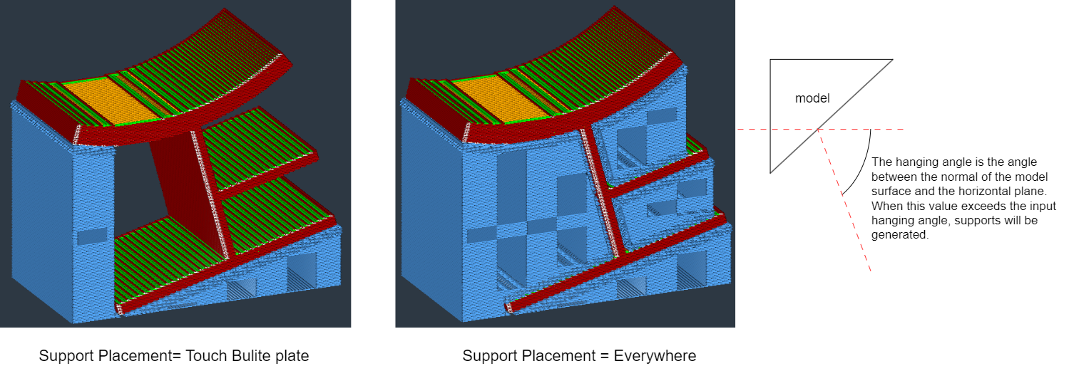 |
| 3 | Support Overhang Angle | Add the minimum overhang angle for support. A value of 0° means all overhangs will have support, while 90° means no support will be provided. The overhang angle for support is the minimum slope angle that requires support. If the slope angle of a surface's normal to the horizontal line is greater than this threshold, and the support type is set to automatic, support will be generated automatically. | |
| 4 | Support Structure | Choose different types of support: normal support and tree-like support. |
 |
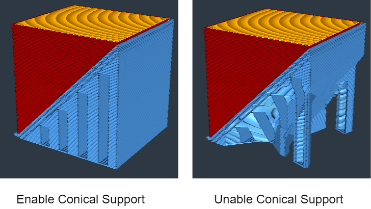
| 5 | Enable Conical Support | Enable Conical support so that the support area at the bottom is either smaller or larger than the overhanging area. |
 |
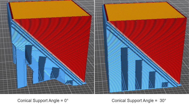
| 6 | Conical Support Angle | The incline angle of Conical support affects its stability. Supports with smaller angles are stronger but require more material. An angle less than 0 makes the base of the support wider, 0 degrees represents vertical support, and 90 degrees represents horizontal support. |
 |
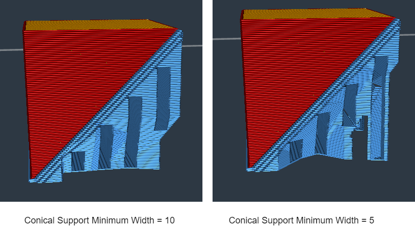
| 7 | Conical Support Minimum Width | The minimum width of the base area of the Conical support. The width should not be too small, as this may lead to an unstable support structure. |
 |
| 8 | Support Z Distance | The distance from the top/bottom surface of the support structure to the bottom/top surface of the printed part. This gap provides space for removing the support after the model is printed. The parameter is automatically rounded to the nearest integer multiple of the layer height. |
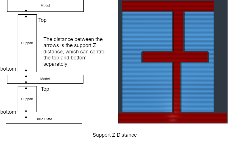 |
| 9 | Support Z Distance-Top | The distance from the top of the support to the overhanging surface of the printed part. | |
| 10 | Support Z Distance-Bottom | The distance from the printed part to the bottom of the support. | |
| 11 |
Support Distance Priority
|
If the X/Y distance takes priority over the Z distance, then the X/Y distance will remain unchanged, even if the Z distance exceeds the set value. If the Z distance takes priority over the X/Y distance, then the Z distance will remain unchanged, even if the X/Y distance is less than the expected value. In positions where the Z distance does not have an impact, the X/Y distance will affect the printing; therefore, it will not affect the top of the support structure, only the sides. However, the minimum X/Y distance will still be adhered to. |
 |
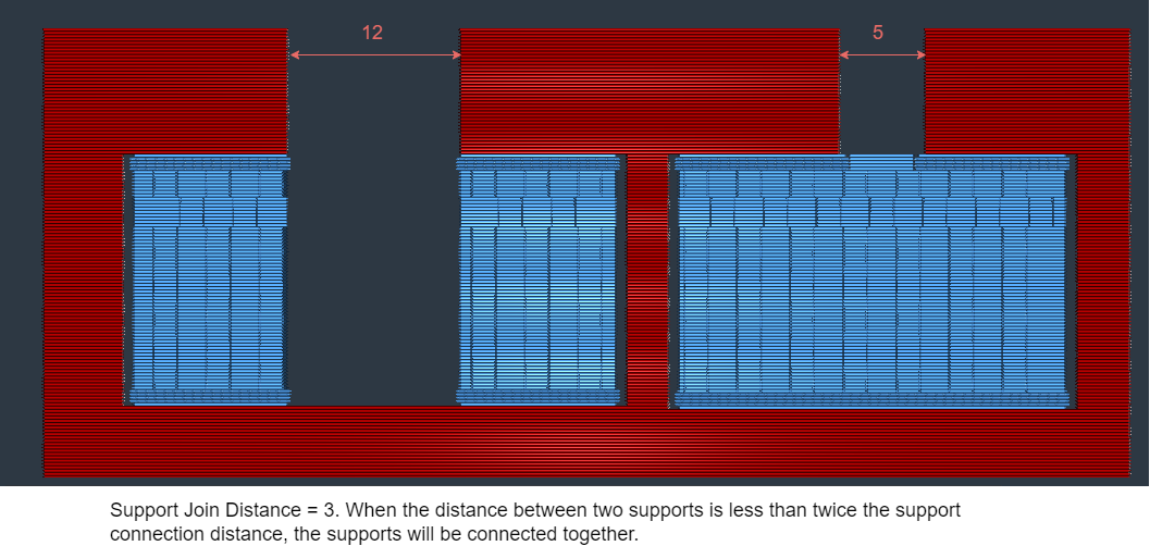
| 12 | Support Join Distance | The maximum distance of the support structure in the X/Y direction. When the independent support distance is smaller than the set value, the support structures will combine into a single support. |
 |
| 13 | Support X/Y Distance | The distance between the support structure and the printed object in the X/Y direction. |
 |
| 14 | Minimum Support X/Y Distance | The distance between the support structure and the overhang surface in the X/Y direction. | |
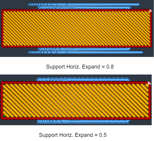
| 15 | Support Horiz. Expand | The distance that the support extends beyond the width of the model on the horizontal plane, to provide better support for the model. |
 |
¶ Support structure = Normal
| Parameter name | Parameter meaning | The impact of parameter adjustments on the NEO | |
|---|---|---|---|
| 1 | Support Pattern | The pattern of the printed support structure varies. Different forms of support styles have different support effects and varying levels of difficulty for removal. |
 |
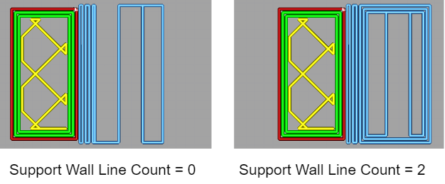
| 2 | Support Wall Line Count | The number of walls printed around the support structure can be adjusted. Adding an extra wall line can make the support printing more reliable and better support the model, but it will also increase the printing time and the amount of material used. |
 |
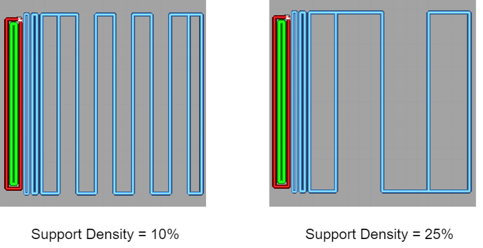
| 3 | Support Density | Adjust the density of the support structure. Higher values will produce better support structures, but the supports will be more difficult to remove. |
 |
| 4 | Support Line Distance | The distance between the lines of the printed support structure is calculated based on the support density setting. | |
| 5 | Support Line Directions | An array of integer line direction angles to be used. As the layers progress, the angles listed in the array are used in sequence, and when the end of the list is reached, it starts over from the first angle. The items in the list are separated by commas, and the entire list is enclosed in square brackets. The default is an empty list, which means that the traditional default angles (45 degrees and 135 degrees) will be used. | |
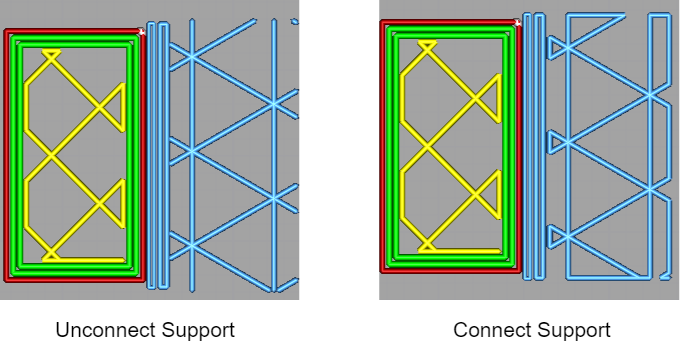
| 6 | Connect Support ZigZags | Connecting supports, when enabled, will increase the strength of the zigzag support structure. |
 |
| 7 | Initial Layer Support Pattern | The pattern of the initial layer of the support structure. Different forms of support styles have varying effects on support performance and ease of removal. | |
| 8 | Initial Support Layers | The number of layers for the initial support of the support structure. | |
| 9 | Initial Layer Support Line Distance | The distance between the lines of the initial layer support structure. |
¶ Support structure = Tree
| Parameter name | Parameter meaning | The impact of parameter adjustments on the NEO | |
|---|---|---|---|
| 1 | Tree Support Branch Angle | This setting determines the maximum overhang angle allowed for the branches of tree-like supports. Increasing the angle allows the branches to print more horizontally, enabling them to extend further. Decreasing the branch angle will make the branches more vertical, while increasing the angle will make them more horizontal. |
 |
| 2 | Tree Support Branch Distance | The distance between the individual branches when they come into contact with the model. Making this distance too small will result in more contact points between the tree supports and the model, providing better overhang support but making the supports more difficult to remove. | |
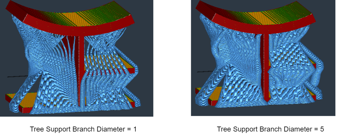
| 3 | Tree Support Branch Diameter | The diameter of the thinnest branches of the tree-like supports. The larger the branch diameter, the sturdier it will be. The branches at the bottom will be larger than this diameter. |
 |
| 4 | Tree Support Maximum Diameter | The diameter of the widest branches of the tree-like supports. The larger the branch diameter, the sturdier it will be; a thinner branch occupies less print space. | |
| 5 | Tree Support Branch Diameter Angle | The angle at which the branch diameter gradually thickens toward the bottom. An angle of 0 indicates that the branch has a uniform thickness along its entire length. A slight angle can enhance the stability of the tree-like supports. | |
| 6 | Tree Support Collision Resolution | The tree-like support collision resolution is used to calculate the resolution for collision detection, aiming to avoid collision models. Setting this to a lower value will result in more accurate and generally fewer failed trees, but it will significantly increase slicing time. |
¶ Support Interface
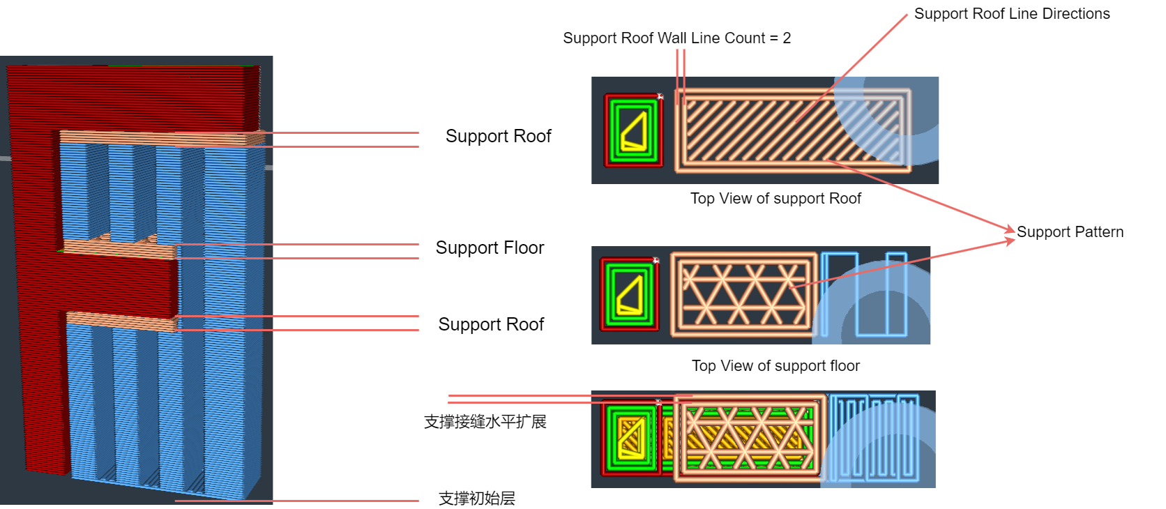
支撑接缝是指在3D打印过程中,用于连接支撑结构和打印件的特定区域。这个区域通常由较薄的层组成,旨在提供足够的支撑力,同时尽量减少对打印件表面质量的影响。
| Parameter name | Parameter meaning | The impact of parameter adjustments on the NEO | |
|---|---|---|---|
| 1 | Enable Support Interface | Generate support seams between the model and the support. |
 |
| 2 | Support Interface Thickness | The thickness of the interface between the supports and the bottom or top of the model. |
 |
| 3 | Support Interface Pattern | The infill pattern style for printing support seams. | |
| 4 | Support Interface Wall Line Count | The number of walls surrounding the support seams. Increasing the number of walls can enhance the reliability of printing supports and provide better support for overhanging sections, but it may also increase printing time and material usage. | |
| 5 | Support Interface Density | Adjusting the density of the top and bottom surfaces of the support structure. Higher values will result in better overhangs, but the supports will be more difficult to remove. | |
| 6 | Minimum Support Interface Area | The minimum area of the support seam polygons. Polygons with an area smaller than this value will be printed as regular supports. | |
| 7 | Support Interface Horiz Expand | The horizontal offset applied to support the support model. | |
| 8 | Support Interface Line Directions | The list of integer row directions to be used. As the layers progress, the elements in the list are used sequentially. When the end of the list is reached, it starts again from the beginning. The list items are separated by commas and enclosed in brackets. By default, it is an empty list, which means it alternates between 45 to 135 degrees or 90 degrees if the support seam is thick. |
¶ Support Roof
| Parameter name | Parameter meaning | |
|---|---|---|
| 1 | Enable Support Roof | Generate support interface layers between the roof of the support and the model. By default, the density of the support interface is higher than regular support. |
| 2 | Support Roof Thickness | The thickness of the roof of the support. This determines the number of support roof seams. |
| 3 | Support Roof Pattern | The pattern style of the support roof seams. |
| 4 | Support Roof Wall Line Count | The number of walls surrounding the support roof seams. |
| 5 | Support Roof Density | The density of the support roof structure. Higher values result in better sagging, but make the support structures more difficult to remove. |
| 6 | Support Roof Line Distance | Print the distance between the top lines of the supports. This setting is calculated based on the top density of the supports, but can be adjusted independently. |
| 7 | Minimum Support Roof Area | The minimum area for a support top seam. Support seams with an area smaller than this value will be printed as regular supports. |
| 8 | Support Roof Horiz Expand | The horizontal extension amount of the support Roof seam. |
| 9 | Support Roof Line Directions | The list of integer row directions to be used. As the layers progress, the elements in the list are used sequentially. When the end of the list is reached, it starts again from the beginning. The list items are separated by commas and enclosed in brackets. By default, it is an empty list, which means it alternates between 45 to 135 degrees or 90 degrees if the support seam is thick. |
¶ Support Floor
| Parameter name | Parameter meaning | |
|---|---|---|
| 1 | Enable Support Floor | Generate support interface layers between the bottom of the support and the model. By default, the density of the support interface is higher than regular support. |
| 2 | Support Floor Thickness | The thickness of the floor of the support. This determines the number of support roof seams. |
| 3 | Support Floor Pattern | The pattern style of the support floor seams. |
| 4 | Support Floor Wall Line Count | The number of walls surrounding the support floor seams. |
| 5 | Support Floor Density | The density of the support floor structure. Higher values result in better sagging, but make the support structures more difficult to remove. |
| 6 | Support Floor Line Distance | Print the distance between the top lines of the supports. This setting is calculated based on the floor density of the supports, but can be adjusted independently. |
| 7 | Minimum Support Floor Area | The minimum area for a support floor seam. Support seams with an area smaller than this value will be printed as regular supports. |
| 8 | Support Floor Horiz Expand | The horizontal extension amount of the support floor seam. |
| 9 | Support Floor Line Directions | The list of integer row directions to be used. As the layers progress, the elements in the list are used sequentially. When the end of the list is reached, it starts again from the beginning. The list items are separated by commas and enclosed in brackets. By default, it is an empty list, which means it alternates between 45 to 135 degrees or 90 degrees if the support seam is thick. |
¶ Support Skin
| Parameter name | Parameter meaning | |
|---|---|---|
| 1 | Support Skin Layers | The number of layers in the interface skin of the support where it comes into contact with either the top or bottom surface of the model. |
| 2 | Support Roof Skin Layers | The layer count of the interface skin between the support and the model at their top contact point. |
| 3 | Support Floor Skin Layers | The layer count of the interface skin between the support and the model at their bottom contact point. |