¶ Material Parameters
Print temperature is a critical parameter in the 3D printing process as it directly affects print quality, material performance, and print success rates. Adjusting the appropriate print temperature ensures proper material melting and adhesion, resulting in high-quality prints. Here are the concepts and main impacts of print temperature.
¶ Temperature
¶ Concept
Print temperature
Print temperature refers to the temperature at which the nozzle (or extruder) is heated during the 3D printing process to melt and extrude the chosen printing material, such as PLA, ABS, PETG, etc.
¶ Main Impacts
1. Material melting and extrusion:
Different types of printing materials, like PLA, ABS, PETG, have their own melting points and ideal print temperatures. Proper temperature settings ensure the material melts and extrudes smoothly through the nozzle. If the temperature is too low, the material may not fully melt, leading to inconsistent extrusion or nozzle clogging. If the temperature is too high, the material may become too liquid, resulting in print overflow or reduced print quality.
2. Interlayer adhesion:
Appropriate print temperature ensures each layer adheres well to the previous layer after extrusion, ensuring print strength and integrity. If the temperature is too low, interlayer adhesion may be insufficient, leading to delamination or fragile parts. If the temperature is too high, it may reduce the shape accuracy of the print.
3. Surface quality:
Temperature settings significantly impact the surface smoothness and details of the print. Excessive temperature can cause material overflow and result in an uneven surface or stringing. Insufficient temperature may lead to surface roughness or "warping" marks.
4. Print speed:
Print temperature is closely related to print speed. Higher print speeds require higher temperatures to ensure timely melting and smooth extrusion of the material. Conversely, lower print speeds allow for a reduction in print temperature.
5. Material characteristics:
Different materials have varying temperature requirements. For example, the ideal print temperature for PLA typically ranges from 180-220°C, while ABS ranges from 230-260°C. Understanding and following the recommended print temperature for each material ensures print quality and performance.
Parameter name |
Parameter meaning |
|
|---|---|---|
| 1 | Print Temperature | The temperature of the printer nozzle during printing. |
| 2 | First Layer Print Temperature | The temperature of the first layer can be set to 0 to disable special treatment for the first layer temperature. |
| 3 | Initial Print Temperature | The "Initial Printing Temperature" signifies the lowest temperature reached when heating up to the printing temperature for printing to start. |
| 4 | Final Print Temperature | The temperature at which cooling has already begun before printing ends. |
| 5 | Standby Temperature | The nozzle temperature during idle times when printing has not yet commenced. |
| 6 | Build Plate Temperature | The temperature used for heating the build plate. If the temperature is 0, the build plate will not be heated. |
| 7 | Chamber Temperature | The chamber temperature maintained during printing. If the temperature is 0, the chamber temperature will not be adjusted. |
¶ Temperatur parameters in Neo
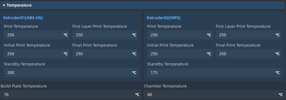
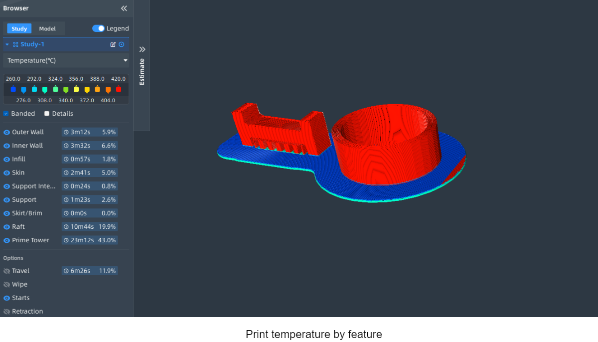
¶ Temperatur shown in Neo
Different features can be printed by controlling the temperature of the Raft bottom layer, middle layer, skin layer and initial layer:
¶ Flow
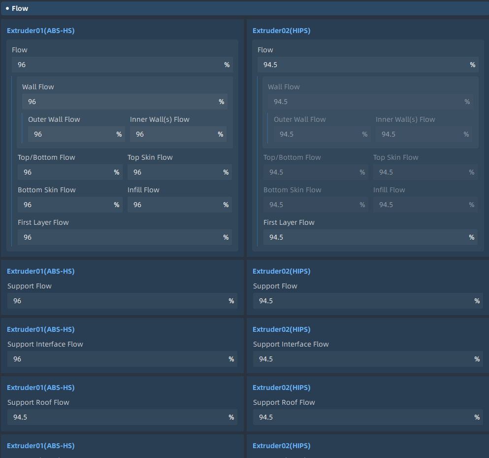
Flow rate refers to the amount of material extruded from the nozzle during the 3D printing process. It is usually expressed as a percentage and adjusted based on the default setting of 100% in slicing software. For example, setting the flow rate to 110% means extruding 10% more material than the default setting, while setting it to 90% means extruding 10% less material than the default setting.
Parameter name |
Parameter meaning |
|
|---|---|---|
| 1 | Flow | Flow compensation, where the extruded material amount is multiplied by this value to obtain the actual material amount. |
| 2 | Wall Flow | Flow compensation for the wall lines during printing. |
| 3 | Outer Wall Flow | Flow compensation for the outer wall lines during printing. |
| 4 | Inner Wall(s) Flow | Flow compensation for the inner wall lines during printing. |
| 5 | Top/Bottom Flow | Flow compensation for the top/bottom surfaces, excluding the top and bottom skin layers during printing. |
| 6 | Top Skin Flow | Flow compensation for the top surface skin during printing. |
| 7 | Bottom Skin Flow | Flow compensation for the bottom surface skin during printing. |
| 8 | Infill Flow | Flow compensation for the infill lines during printing. |
| 9 | First Layer Flow | Flow compensation for the first layer, where the extruded flow is multiplied by this value to achieve the desired material amount. |
| 10 | Support Flow | Flow compensation for the support structures during printing. |
| 11 | Support Interface Flow | Flow compensation for the support interface during printing. |
| 12 | Support Roof Flow | Flow compensation for the support Roof interface during printing. |
| 13 | Support Floor Flow | Flow compensation for the support Floor interface during printing. |
¶ Retraction
During the printing process, the tool head constantly moves, often resulting in a significant amount of travel paths. We do not want the nozzle to extrude filament during these travel movements. However, due to the temperature of the nozzle and the internal pressure, molten filament may still leak from the nozzle, leaving behind stringing artifacts on the printed part. Retraction settings can help reduce and alleviate stringing during printing. By retracting some filament from the printer's hot end before the tool head moves during travel, the pressure of the molten filament in the hot end can be reduced, thereby decreasing the likelihood of stringing on the travel paths. Retraction typically occurs before the travel movement, and at the end of the travel, the filament is refilled back into the hot end to ensure normal flow, ensuring that the printed part is not under-extruded.
Parameter name |
Parameter meaning |
|
|---|---|---|
| 1 | Enable Retraction | Enable retraction when the nozzle moves in non-printing areas. |
| 2 | Retraction Distance | Length of material retracted during retraction. |
| 3 | Retract at Layer Change | Enable retraction when the nozzle moves to the next layer. |
| 4 | Retraction Speed | Retraction speed for both filament and infill during retraction movement. |
| 5 | Retraction Retract Speed | Retraction speed for filament during retraction. |
| 6 | Retraction Prime Speed | The speed of material refill during retraction. |
| 7 | Retraction Prime Speed at Z Seam | The retraction speed of the material at the Z-seam during retraction. |
| 8 | Retraction Prime Speed at Z Seam | The speed of material deposition at the Z-seam during retraction. |
| 9 | Retraction Extra Prime | The additional deposition of material during retraction can be a negative value, as some materials ooze during movement, compensating for this can be achieved by setting a negative value here. |
| 10 | Retraction Extra Prime at Z Seam | The additional material deposition at the Z-seam during retraction. |
| 11 | Retraction Minimum Travel | The minimum travel distance required for retraction to occur, preventing retraction during very short movements, where the material has little time to ooze from the nozzle, making retraction more harmful than beneficial. |
| 12 | Maximum Retract Count | This setting limits the number of retractions that can occur within a minimum extrusion distance window. Any retractions exceeding this limit within the window will be ignored. This prevents excessive retractions on the same filament, which can flatten the filament and lead to issues with filament feed. |
| 13 | Minimum Extrusion Distance | Enforce a fixed range for the maximum retraction count. This value should be approximately the same as the retraction distance, effectively limiting the number of retractions through the same filament segment. |
| 14 | Switch Retraction Distance | The retraction distance when switching nozzles, set to 0 to disable retraction entirely. This distance should generally be the same as the length of the nozzle heating zone. |
| 15 | Nozzle Switch Retraction Speed | The retraction speed for filament. Higher retraction speeds typically yield better results, but excessively high retraction speeds can cause filament slip. |
| 16 | Switch Retract Speed | The retraction speed for material when switching nozzles. Higher retraction speeds usually yield better results, but excessively high retraction speeds can cause filament slip. |
| 17 | Switch Prime Speed | The speed at which filament is loaded after nozzle switching. |
¶ Fan Control
The filament extruded from the extruder typically has a temperature ranging from 190°C to 240°C. At this temperature, the filament is hot and soft, allowing it to be shaped into different forms. However, once it cools down, it quickly solidifies and sets. Therefore, it is essential to find a balance between temperature and cooling to ensure smooth flow of the filament from the nozzle while allowing it to solidify quickly. Failure to achieve this balance can result in inaccuracies in the shape of the printed object. Increasing the airflow from the fan can expedite the cooling process. However, if you have set a very fast printing speed, the previous layer may not have cooled down before the new layer is being deposited on top of it, potentially causing damage to the model. This is particularly important when printing small models as each layer has a short printing time. You can address this by setting a minimum print time per layer, allowing sufficient time for cooling and solidification.

Parameter name |
Parameter meaning |
|
|---|---|---|
| 1 | Enable Print Cooling | Enabling the print cooling fan during printing can improve the print quality of small features, overhangs, and bridging surfaces. |
| 2 | Fan Speed | The rotation speed of the print cooling fan during printing. |
| 4 | Regular Fan Speed | The rotation speed of the fan before reaching the threshold, and gradually switching to maximum speed when the print speed of a particular layer exceeds the threshold. |
| 5 | Maximum Fan Speed | The rotation speed of the fan during the minimum layer time (the shortest time set to print a layer), gradually increasing between normal and maximum fan speed when the threshold is reached. |
| 6 | Initial Fan Speed | The rotation speed of the print head fan at the beginning of printing (first few layers), then the fan speed will gradually transition to the normal speed. |
| 7 | Maximum Fan Threshold | The layer time at which the threshold is set between the normal and maximum fan speeds. Layers with print speeds slower than this time will use the normal fan speed. For layers with faster speeds, the fan rotation speed gradually increases to the maximum speed. In practice, reducing this threshold (towards shorter layers) will result in the fan rotating more frequently at the normal speed. Increasing this threshold will cause the fan to rotate more frequently at higher speeds, even when the layers are not very small. It is best to maintain a certain distance between the minimum layer time and the normal/maximum fan speed threshold. If the threshold is set to the "minimum layer time" (the shortest time set to print a layer), the fan will suddenly stop when the layer count is slightly below the threshold. This will result in visible stripes on the printed surface, as the sudden opening of the fan will create a hard edge. In contrast, if there is some difference between the two settings, the change in fan speed will be more gradual, and no stripes will be visible during printing. |
| 8 | Regular Fan Speed at Layer | The layer at which the fan starts rotating at the normal fan speed. |
| 9 | Enable Auto Cooling Control | Automatic control of the cooling fan during printing. |
| 10 | Lift Head | When the minimum layer time is reached and the minimum speed is reached, the printhead is lifted off the print and an additional wait is added until the minimum print layer time is reached. |
| 11 | Minimum Layer Time | The minimum time spent in a layer, which forces the printer to slow down to at least the time set for a layer, allowing the printed material to cool properly before printing the next layer. If the "Lift Head" or "Minimum Speed" restrictions are turned off, the time required for this layer may still be less than the minimum layer time. |
| 12 | Minimum Speed | The minimum printing speed, although reduced due to the minimum single layer printing time. When the printing speed is too slow, the pressure in the nozzle is too low, resulting in poor print quality. |
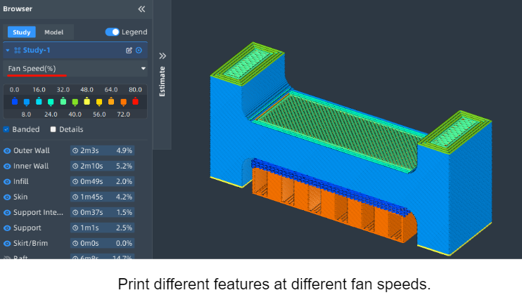
| 13 | Fan Speed Override | The fan speed can be controlled based on the printing characteristics. |
| 14 | Outer Wall Fan Speed | The fan speed percentage used when printing with specific characteristics. |
| 15 | Inner Wall Fan Speed | The fan speed percentage used when printing with specific characteristics. |
| 16 | Top Skin Fan Speed | The fan speed percentage used when printing with specific characteristics. |
| 17 | Bottom Skin Fan Speed | The fan speed percentage used when printing with specific characteristics. |
| 18 | Top Skin Outer Wall Fan Speed | The fan speed percentage used when printing with specific characteristics. |
| 19 | Top Skin Inner Wall Fan Speed | The fan speed percentage used when printing with specific characteristics. |
| 20 | Bottom Skin Outer Wall Fan Speed | The fan speed percentage used when printing with specific characteristics. |
| 21 | Bottom Skin Inner Wall Fan Speed | The fan speed percentage used when printing with specific characteristics. |
| 22 | Top Layers Fan Speed | The fan speed percentage used when printing with specific characteristics. |
| 23 | Bottom Layers Fan Speed | The fan speed percentage used when printing with specific characteristics. |
| 24 | Infill Fan Speed | The fan speed percentage used when printing with specific characteristics. |
| 25 | Support Infill Fan Speed | The fan speed percentage used when printing with specific characteristics. |
| 26 | Support Roof Fan Speed | The fan speed percentage used when printing with specific characteristics. |
| 27 | Support Roof Skin Fan Speed | The fan speed percentage used when printing with specific characteristics. |
| 28 | Support Bottom Fan Speed | The fan speed percentage used when printing with specific characteristics. |
| 29 | Support Bottom Fan Speed | The fan speed percentage used when printing with specific characteristics. |
¶ Nozzle control
The nozzle of a 3D printer is a crucial component that determines the accuracy and quality of the printed object. It is responsible for extruding the filament and depositing it layer by layer. Proper control of the nozzle is essential for achieving desired results.
To control the nozzle, several factors need to be considered:
1. Nozzle Temperature: The temperature of the nozzle plays a vital role in melting the filament and ensuring smooth extrusion. Different materials require different nozzle temperatures for optimal printing results.
2. Nozzle Size: The size of the nozzle determines the width of the extruded filament. Smaller nozzles result in finer details but may increase printing time, while larger nozzles allow for faster printing but with less precision.
3. Nozzle Height/Leveling: The nozzle needs to be properly leveled and positioned at the correct height above the print bed. This ensures consistent filament deposition and prevents issues such as uneven layers or adhesion problems.
4. Nozzle Cleaning: Regular cleaning of the nozzle is necessary to prevent clogs or blockages. Filament residue or debris can accumulate over time, affecting print quality. Cleaning methods may include using a nozzle cleaning needle or performing a cold or hot pull.
By carefully controlling and maintaining the nozzle, you can optimize the printing process and achieve high-quality prints.
Parameter name |
Parameter meaning |
|
|---|---|---|
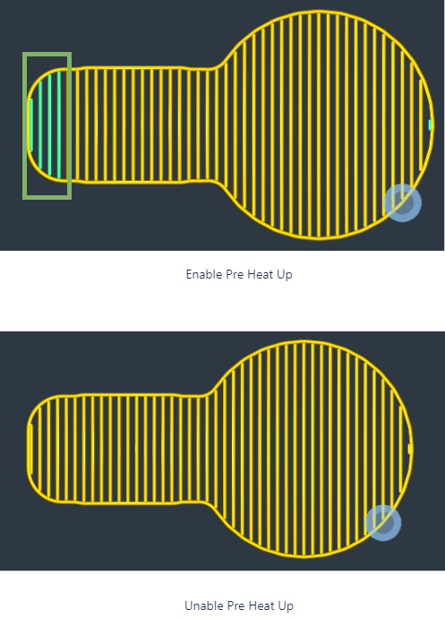
| 1 | Enable Pre Heat Up | Enable Pre Heat Up |
| 2 | Nozzle Heat Up Speed | The speed (°c/s) by which the nozzle heats up averaged over the window of normal printing temperatures and the standby temperature. |
| 3 | Nozzle Cool Down Speed | The speed (°c/s) by which the nozzle cools down average dover the window of normal printing temperatures and the standby temperature. |
¶ Nozzle control parameters

¶ Nozzle control Pre Heat Up
¶ Shrinkage Compensation
During the 3D printing process, the material undergoes two phase transitions from solid to liquid and back to solid. When the material solidifies, the stress deformation caused by material shrinkage can affect the accuracy of the printed object. If the material used in the printing process is known, this error can be eliminated by setting the "shrinkage compensation factor" in the slicing software for size compensation in the X, Y, and Z directions.
Parameter name |
Parameter meaning |
|
|---|---|---|
| 1 | Enable Shrinkage Compensation | Enable Shrinkage Compensation |
| 2 | X Shrinkage Compensation Ratio | X Shrinkage Compensation Ratio |
| 3 | Y Shrinkage Compensation Ratio | Y Shrinkage Compensation Ratio |
| 4 | Z Shrinkage Compensation Ratio | Z Shrinkage Compensation Ratio |