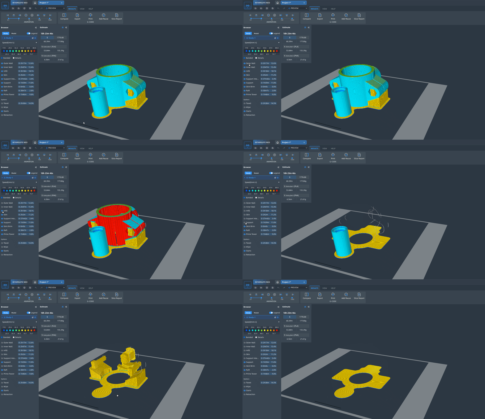
¶ Printing speed
In 3D printing, different features require different printing speeds. Properly controlling the printing speed can significantly impact the final print quality, precision, and stability.
¶ parameters Setting
| parameter name | parameter meaning | |
|---|---|---|
| 1 | Print Speed | The printing speed. |
| 2 | Infill Speed | The printing speed of infill |
| 3 | Wall Speed | The printing speed of the walls. |
| 4 | Outer Wall Speed | Printing the outer wall at as lower speed improves skin quality, but having a large difference between inner and outer wall speeds negatively affects quality. |
| 5 | Inner Wall Speed | The speed at which the inner walls are printed can be optimized to reduce printing time by setting it between the speeds of the outer wall and infill. |
| 6 | Top/Bottom Speed | The printing speed of the top and bottom layers. |
| 7 | Top Speed | The printing speed of the top layers. |
| 8 | Bottom Speed | The printing speed of the bottom layers. |
| 9 | Top Skin Speed | The printing speed of the top surface skin layers. |
| 10 | Top Skin Outer Wall Speed | The printing speed of the outer wall of the top surface skin layers. |
| 11 | Top Skin Inner Wall Speed | The printing speed of the inner wall of the top surface skin layers. |
| 12 | Top Skin Infill Speed | The printing speed of the infill area in the top surface skin layers. |
| 13 | Bottom Skin Outer Wall Speed | The printing speed of the bottom surface skin layers. |
| 14 | Bottom Skin Inner Wall Speed | The printing speed of the outer wall of the bottom surface skin layers. |
| 15 | Bottom Skin Infill Speed | The printing speed of the inner wall of the bottom surface skin layers. |
| 16 | Bottom Skin Infill Speed | The printing speed of the infill area in the bottom surface skin layers. |
| 17 | Support Infill Speed | The printing speed of the infill support affects its stability. and lower speeds can enhance this aspect. |
| 18 | Support Interface Speed | Lower the printing speed of support roofs and floors to enhance overhang quality. |
| 19 | Support Roof Speed | Print support roofs at lower speeds for better overhang quality. |
| 20 | Support Floor Speed | Print support floor at lower speed for improved adhesion on top of your model. |
| 21 | Support Roof Skin Speed | Improve overhang quality by printing roof skins of support at lower speeds. |
| 22 | Support Floor Skin Speed | Enhance adhesion of support on top of your model by printing floor skins at a slower speed. |
| 23 | Travel Speed | The speed at which travel movements are executed. |
| 24 | First Layer Speed | The speed for the first layer. A lower value is advised to improve adhesion to the build plate. |
| 25 | First Layer Print Speed | The printing speed for the first layer. A lower value is recommended to enhance adhesion to the build plate. |
| 26 | First Layer Travel Speed | The travel speed should be lower to avoid pulling printed parts from the build plate. This value can be calculated based on the ratio between travel speed and print speed. |
| 27 | Maximum Z Speed | The maximum speed of the build plate. Setting to zero uses firmware defaults for Maximum Z Speed. |
| 28 | Z Hop Speed | The Z Hops' vertical movement speed is usually slower than the print speed due to the difficulty in moving the build plate |
| 29 | Equalize Filament Flow | Print thinner lines faster to maintain the same extrusion rate. Smaller line widths maybe needed for thin parts in your model, and this setting adjusts the speed changes accordingly. |
| 30 | Maximum Speed for Equal Flow | Maximum print speed when equalizing flow by adjusting speed. |
| 31 | Number of Slower Layers | The initial layers are printed slower for better adhesion and success. Gradually increasing speed after these layers. Lower value recommended for first layer adhesion. |
| 32 | Wipe Speed | Wipe Speed. |
| 33 | Wipe Speed | Wipe Speed. |
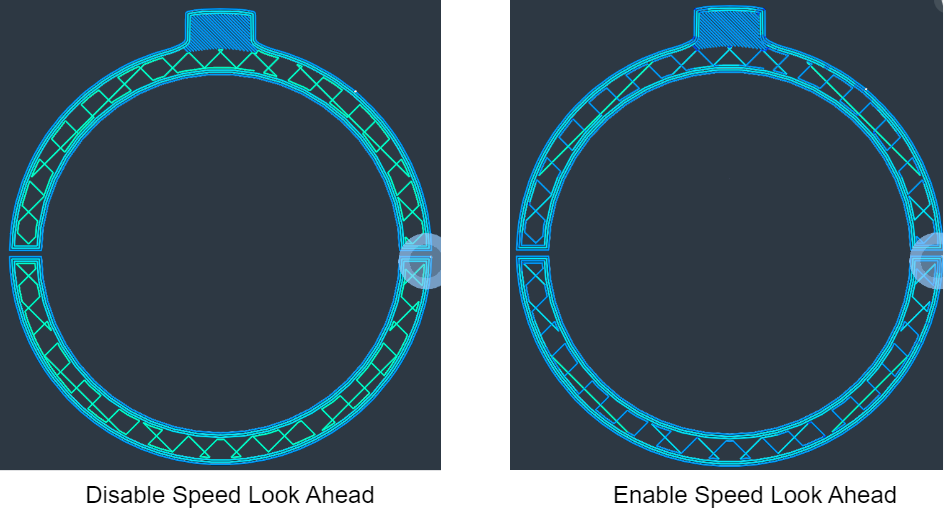
| 34 | Enable Speed Look Ahead | Enable Speed Look Ahead. |
| 35 | Combing Speed | Combing Speed |
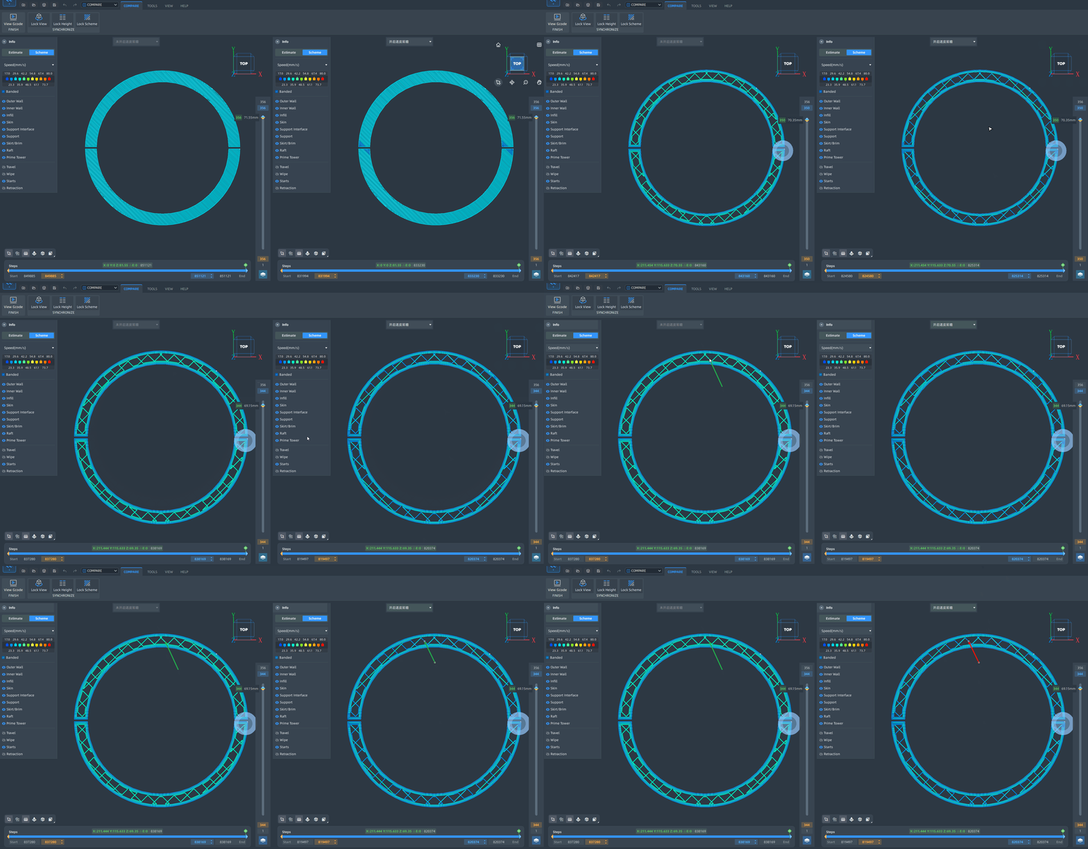
¶ Check the printing speed for different features

¶ Look Ahead
Look-Ahead is a technique commonly used in CNC machining and 3D printing to optimize and adjust the motion path and speed of the machine, thereby improving the efficiency and quality of machining or printing. Look-Ahead primarily works by analyzing upcoming path segments in advance and preemptively adjusting speed and acceleration to achieve smooth and efficient motion. Below are the main roles and principles of Look-Ahead:
¶ Main Roles
Increase Printing Speed:
- Look-Ahead technology allows for faster speed adjustments without compromising print quality by analyzing the path in advance, thus increasing overall printing speed.
Improve Print Quality:
- By ensuring smooth transitions and preemptively decelerating, Look-Ahead can reduce surface defects such as vibrations and ripples, thereby enhancing the surface quality and accuracy of the final print.
Reduce Vibrations and Shaking:
- When the print path changes abruptly, Look-Ahead can preemptively decelerate to minimize mechanical vibrations caused by sudden accelerations or decelerations, thereby improving printer stability.
Increase Path Accuracy:
- For complex paths, Look-Ahead can plan in advance, allowing the printer to move more smoothly at turns or changes, ensuring geometric accuracy of the print.
¶ Principles
Path Segment Analysis:
- During the actual printing process, the Look-Ahead algorithm analyzes multiple path segments in advance, not just the current segment. This pre-analysis helps the system understand upcoming path changes and make appropriate speed and acceleration adjustments.
Smooth Transitions:
- Based on the information from Look-Ahead path segments, the system can preemptively decelerate or accelerate to ensure smooth transitions at path changes (such as corners or curves), reducing impact and vibrations.
Dynamic Speed and Acceleration Adjustment:
- By dynamically adjusting speed and acceleration, Look-Ahead technology can strike a balance between complex paths and high speeds, achieving both efficient and high-quality printing.


¶ Acceleration/Jerk Control
¶ Acceleration Control Function
Increase Printing Speed: Quickly reach target speed: Acceleration control determines the time it takes for the printer to go from a stationary or low-speed state to the target printing speed. Higher acceleration settings can enable the printer to reach the target speed faster, thus increasing overall printing speed.
Reduce Printing Time: Optimize path transitions: In complex or curved printing paths, appropriate acceleration control can reduce path transition time, thereby decreasing overall printing time.
Improve Print Quality: Reduce vibrations and jolts: Suitable acceleration settings can minimize vibrations caused by sudden accelerations or decelerations during printing, thereby enhancing the surface quality and precision of the printed parts.
Protect Mechanical Components: Reduce wear: More gradual acceleration settings can lessen the impact on mechanical components and reduce wear, extending the printer's lifespan.
¶ Jerk Control Function
Reduce Printing Defects: Minimize surface imperfections: Jerk control affects the instantaneous speed changes when the printer changes direction. Appropriate jerk speed settings can reduce printing defects caused by sudden direction changes, such as bumps or indentations at corners.
Improve Printing Accuracy: Smooth motion transitions: By controlling jerk speed, the printer can achieve smoother transitions during path changes, thereby enhancing the geometric accuracy and detail of printed parts.
Lower Noise Levels: Reduce mechanical vibrations: Lower jerk speed settings can lessen the mechanical vibrations and noise generated during the printer's movements, improving the stability and quietness of the printing process.
Protect Mechanical Components: Reduce impact forces: Appropriate jerk speed settings can decrease the impact forces during path transitions, reducing wear on mechanical components and extending the device's lifespan.
¶ parameters setting
| parameter name | parameter meaning | |
|---|---|---|
| 1 | Enable Acceleration Control | Adjust print head acceleration to balance printing time and quality. |
| 2 | Print Acceleration | Print Acceleration |
| 3 | Infill Acceleration | Infill Acceleration |
| 4 | Outer Wall Acceleration | Outer Wall Acceleration |
| 5 | Inner Wall Acceleration | Inner Wall Acceleration |
| 6 | Top Acceleration | The acceleration with which top layers are printed. |
| 7 | Bottom Acceleration | The acceleration with which bottom layers are printed. |
| 8 | Top Skin Acceleration | Top Skin Acceleration |
| 9 | Bottom Skin Acceleration | Bottom Skin Acceleration |
| 10 | Support Infill Acceleration | Support Infill Acceleration |
| 11 | Support Roof Acceleration | The acceleration with which the roofs of support are printed. Printing them at lower acceleration can improve overhang quality. |
| 12 | Support Floor Acceleration | The acceleration with which the floors of support are printed. Printing them at lower acceleration can improve adhesion of support on top of your model. |
| 13 | Travel Acceleration | Travel Acceleration |
| 14 | Initial Print Acceleration | Initial Print Acceleration |
| 15 | Initial Travel Acceleration | Initial Travel Acceleration |
| 16 | Travel Acceleration Between Walls | Travel Acceleration Between Walls |
| 17 | Enable Jerk Control | Adjusts print head jerk to optimize printing time and trade off with print quality. |
| 18 | Print Jerk | The maximum velocity change of print head. |
| 19 | Infill jerk | Maximum velocity change for infill printing. |
| 20 | Outer Wall Jerk | Maximum velocity change for outer wall printing. |
| 21 | Inner Wall Jerk | Maximum velocity change for inner wall printing. |
| 22 | Top Jerk | The maximum instantaneous velocity change with which top layers are printed. |
| 23 | Bottom Jerk | The maximum instantaneous velocity change with which bottom layers are printed. |
| 24 | Top Skin Jerk | Maximum velocity change for top surface skin layers printing. |
| 25 | Bottom Skin Jerk | The maximum instantaneous velocity change with which bottom surface skin layers are printed. |
| 26 | Support infill Jerk | Maximum velocity change for support infill printing. |
| 27 | Support Roof Jerk | The maximum instantaneous velocity change with which the roofs of support are printed. |
| 28 | Support Floor Jerk | The maximum instantaneous velocity change with which the floors of support are printed. |
| 29 | Travel Jerk | The maximum instantaneous velocity change during travel movement. |
| 30 | Initial Print Jerk | The maximum instantaneous velocity change during the printing process of the first layer. |
| 31 | Initial Travel Jerk | The acceleration for travel movements in the first layer. |
| 32 | Travel Jerk Between Walls | Travel jerk between walls |