¶ Path Optimization
¶ Adaptive Line Width
Adaptive Line Width is a 3D printing technique that dynamically adjusts the width of the print path for each layer to optimize print quality and efficiency. This technology is particularly useful in specific scenarios, such as filling gaps, enhancing print speed, and strengthening the structure of the printed object. Below are the main roles, principles, and practical applications of adaptive line width:
¶ Main Roles
Filling Gaps:
- In printing complex structures, a standard fixed line width may not completely fill all areas, leading to small gaps or incomplete fills. Adaptive line width can dynamically adjust the width to fill these gaps, ensuring the integrity and strength of the printed object.
Optimizing Print Speed:
- By adjusting the line width, adaptive line width technology can reduce the number of layers needed, thus speeding up the printing process. For instance, wider line widths can be used in infill areas to accelerate the filling process.
Enhancing Structural Strength:
- Adaptive line width can be adjusted to reinforce specific critical parts of the printed object. For example, wider line widths can be used in areas requiring higher strength, while narrower widths can be used in detailed areas to ensure precision.
Improving Print Quality:
- By dynamically adjusting the line width based on the complexity and geometry of the path, adaptive line width can reduce the risk of over-extrusion or under-extrusion, thereby enhancing print quality and smoothness.
¶ parameters setting
- Wall Transition Length
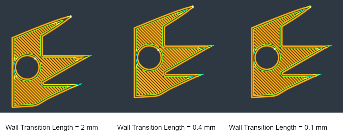
In some cases, the model walls cannot be printed with the regular line width, when the model is too thin. To fix this, the wall line width needs to transition between the number of walls required to fill the model. The wall transition length allows specifying the length of each part before the lines are potentially split again. The impact of this change is mostly visible in the thin parts of this 3D model.
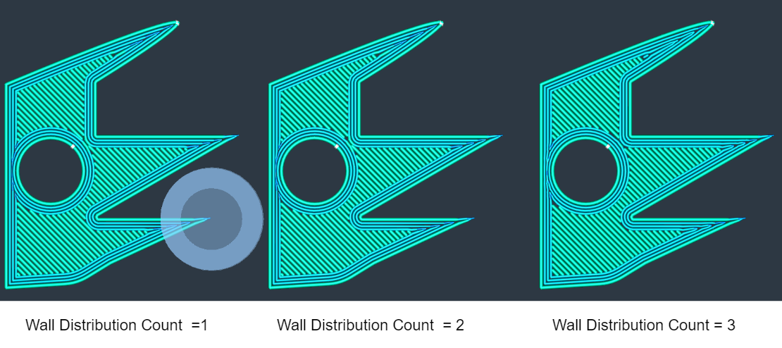
- Wall Distribution Count
The number of walls, counted from the center, over which the variation needs to bespread. Lower values mean that the outer walls don't change in width.
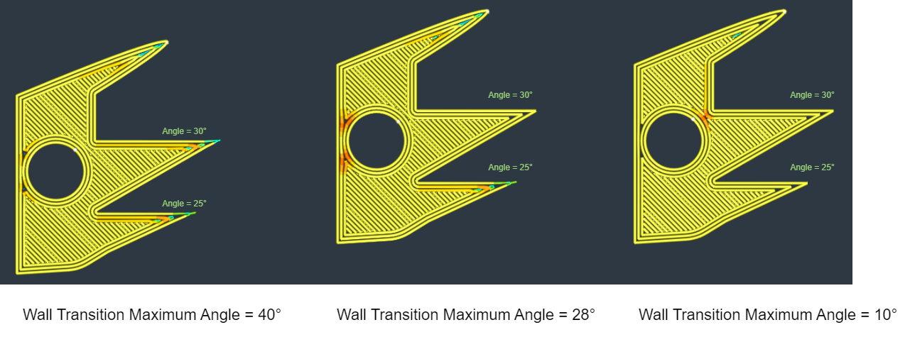
- Wall Transition Maximum Angle
Transitions between even and odd numbers of walls determine if the center space will have printed walls. Reducing this setting decreases the number and length of these center walls, but may result in gaps or over extrusion.
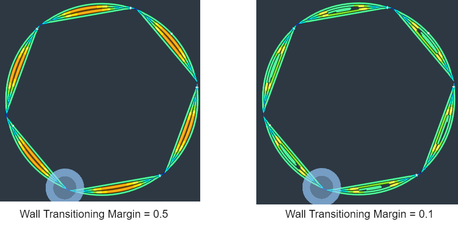
- Wall Transitioning Margin
When printing variable line widths, the lines need to transition from one width to the other. The transition between these widths can be done over a short distance or over a long distance. Increase this margin to reduce the number of transitions, travels, and print start and stops. However, long transitions and line width variations might lead to under- or over-extrusion problems.
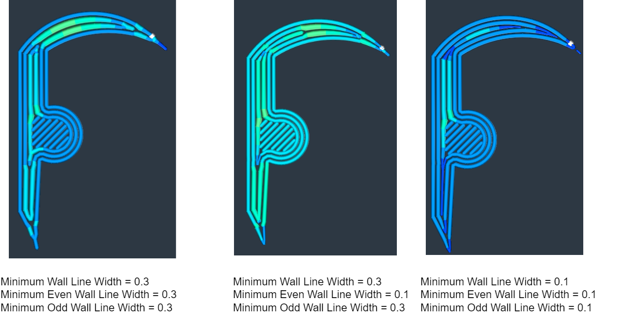
- Minimum Wall Line Width
For structures with a thickness approximately equal to or slightly larger than the nozzle size, it is necessary to adjust the line widths in order to match the model's thickness. This particular setting governs the minimum allowable linewidth for the walls. The minimum line widths also inherently determine the maximum line widths, as we transition from N to N+1 wall sat a certain geometry thickness where N walls are wider and N+1 walls are narrower. The widest possible wall line measures twice the minimum wall line width.
- Minimum Even Wall Line Width
The minimum line width for normal polygonal walls. This setting determines at which model thickness we switch from printing a single thin wall line, to printing two wall lines. A higher Minimum Even Wall Line Width leads to a higher Maximum Odd Wall Line Width. The Maximum Even wall line width is calculated as Outer Wall Line Width + 0.5*Minimum Odd Wall Line Width.
- Minimum Odd Wall Line Width
The minimum line width for middle line gap filler polyline walls. This setting determines at which model thickness we switch from printing two wall lines, to printing two outer walls and a single central wall in the middle. A higher Minimum Odd Wall Line Width leads to a higher Maximum Even Wall Line Width. The Maximum Odd Wall Line Width is calculated as 2 *Minimum Even Wall Line Width.
- Maximum Extrusion Area Deviation
The maximum extrusion area deviation allowed when removing intermediate points from a straight line. An intermediate point may serve as width-changing point in along straight line. Therefore, if it is removed, it will cause the line to have a uniform width and, as a result, lose (or gain)a bit of extrusion area. If you increase this you may notices light under- (or over-)extrusion in between straight parallel walls, as more intermediate width-changing points will be allowed to be removed. Your print will be less accurate, but the g-code will be smaller.
¶ Z-Seam
A Z-Seam (also known as a Z-Scar or Zipper) is the vertical seam that occurs where each layer change begins and ends in a 3D print. It is a visible line or mark on the surface of the print, usually more noticeable in cylindrical or curved objects. The Z-Seam can affect the aesthetics and sometimes the structural integrity of the printed object, so managing it effectively is crucial for high-quality prints.
¶ Main Roles and Considerations
Visual Appearance:
- The Z-Seam is most noticeable on smooth surfaces and can detract from the visual quality of the print. Positioning the seam in less visible areas can help improve the overall appearance.
Structural Integrity:
- Improper seam placement can create weak points in the structure of the print. Ensuring an even distribution of the seam can help maintain the object's strength.
Print Quality:
- Poorly managed Z-Seams can lead to blobs, zits, or other surface imperfections. Fine-tuning the seam settings can help mitigate these issues.
¶ Techniques for Managing Z-Seam
Most slicing software offers settings to control and optimize the location and impact of the Z-Seam. Here are some common techniques:
Seam Hiding (Random or Aligned):
- Random: Placing the seam at random locations on each layer to distribute it evenly across the surface. This can make the seam less noticeable but might introduce surface artifacts.
- Aligned: Placing the seam in a straight line up the side of the print. This can make the seam more noticeable but allows for easier post-processing (e.g., sanding).
Seam Positioning:
- Back or Corner: Positioning the seam at the back or in a corner of the print, where it is less visible.
- Custom Seam Position: Some slicers allow you to set a specific location for the seam, providing more control over its placement.
Wiping and Retraction Settings:
- Wiping: Moving the nozzle slightly away from the seam after finishing a layer to reduce the appearance of blobs.
- Retraction: Pulling back the filament slightly before moving the nozzle to minimize stringing and zits.
¶ parameter setting
- Optimize Z Weld Point Line :Optimize Z Weld Point Line.
- Wipe Retraction Mode:
| Wipe Retraction Mode | G-code |
| No Retract While Wiping | ;WIPE_START G0 F15000 X309.677 Y258.677 ;WIPE_END |
| Retract Before Wiping | G1 X347.988 Y258.443 E303.73363 M205 X20 Y20 ;WIPE_START G1 F7200 X347.847 Y258.302 E303.23363 ;WIPE_END |
| Retract While Wiping | ;WIPE_START G1 F2700 E22.27474 G0 F7200 X309.677 Y258.677 ;WIPE_END |
- Z Weld Point Alignment:
Paths in consecutive layers starting at the same point may create a vertical weld line seam on the print. Aligning these paths near a specified location makes it easier to remove the weld line seam. Random placement of paths reduces noticeable in accuracies at their start. Choosing the shortest path speeds up printing.

- Z Weld Point Position
The position near where to start printing each part in a layer.
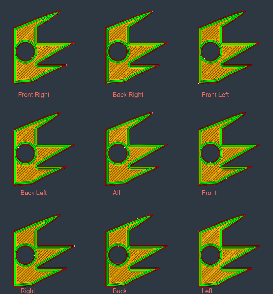
- Z Weld Point X: The X coordinate of the position near where to start printing each part in a layer.
- Z Weld Point Y: The Y coordinate of the position near where to start printing each part in a layer.
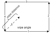
- Outer Wall Wipe Angle: Outer Wall Wipe Angle
- Inner Wall wipe Angle: Inner Wall wipe Angle
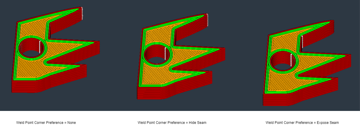
- Weld Point Corner Preference
Corners can control the position of the weld point line. None means no influence. Hide weld point favors inside corners. Expose weld point favors outside corners. Hide or expose allows for both inside and outside corner placement.
- Z Weld Point Relative
When enabled, weld line coordinates are relative to part centers. when disabled, coordinates define an absolute position on the build plate.
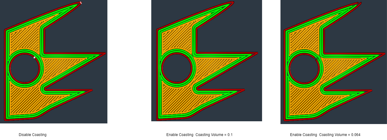
- Enable Coasting
Coasting replaces the end of an extrusion path with a travel path, using oozed material to minimize stringing.
- Coasting Volume
The volume should be close to the nozzle diameter cubed.
- Coasting Speed
The coasting speed should be slightly below 100% of the extrusion path speed to account for pressure drop in the bowden tube.
- Minimum Volume Before Coasting
The minimum extrusion path volume for coasting should be larger than the Coasting Volume, as it scales linearly with smaller paths due to less pressure in the bowden tube.
¶ Printing order
In 3D printing, the printing order refers to the sequence in which different parts of each layer are printed. The choice of this order can significantly affect the quality, strength, and printing time of the printed object. A合理的 printing order can reduce defects, improve surface quality, and optimize printing speed.
In 3D printing, the printing order refers to the sequence in which different parts of each layer are printed. The choice of this order can significantly affect the quality, strength, and printing time of the printed object. A合理的 printing order can reduce defects, improve surface quality, and optimize printing speed.
¶ parameter setting
- Outer Wall wipe Distance
The travel distance could be increased after the outer wall to enhance concealment of the weld seam.
Inner wall wipe Distance: Distance of a travel move inserted after the inner wall, to hide the Z seam better.

- Outer Wall Inset
Apply an inset to the path of the outer wall in cases where the nozzle is larger than the outer wall and it is printed after the inner walls. This offset will ensure that the hole in the nozzle aligns with the inner walls rather than protruding outside of the model.
- Wall Ordering: Inside To Outside、Outside To Inside
Determining the sequence for printing walls is crucial. Prioritizing the printing of outer walls initially enhances dimensional accuracy by preventing any flaws from inner walls to affect the exterior. However, delaying the outer wall printing allows for better stacking when overhangs are being printed.
- Optimize Wall Printing Order
Optimize the sequencing of wall printing to minimize retractions and travel distance. while most parts will benefit from this optimization, it is important to compare print time estimates with and without optimization as some may experience longer printing times. Note that when selecting brim as the build plate adhesion type, the first layer is not optimized.
- Enable Support Wipe
Enable a wiping move at the end of support lines to improve adhesion and prevent material leakage to other areas.
- Enable Skin wipe
Enable a wiping move at the end of infill lines to improve adhesion and prevent material leakage to other areas.
- Enable Infill wipe
Enable a wiping move at the end of skin lines to improve adhesion and prevent material leakage to other areas.
- Other Features Wipe Distance
Distance of wiping move inserted at the end of Support, Infill and Skin lines.
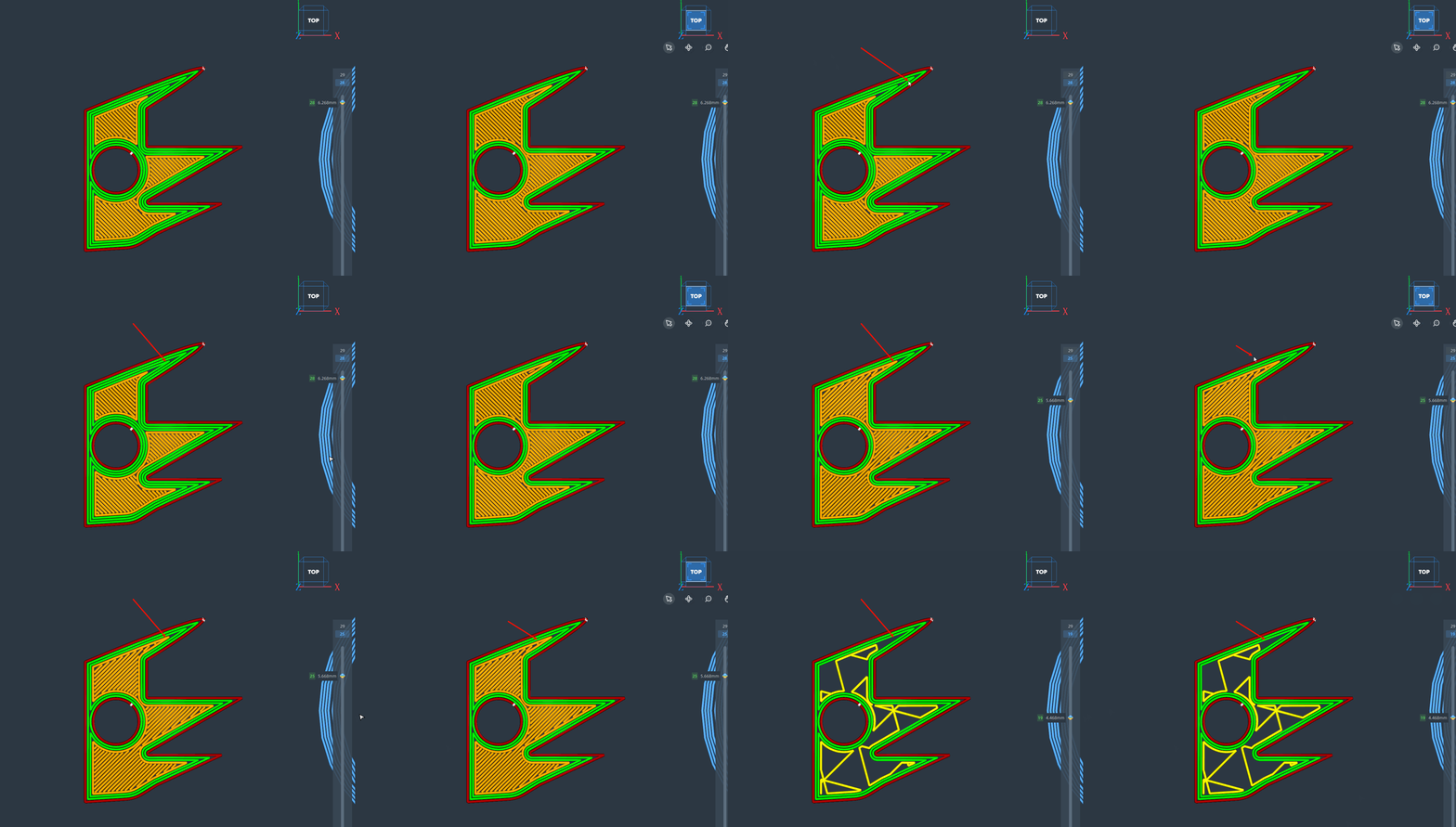
- Alternate Extra Wall
The addition of an additional wall at alternating layers enhances the entrapment of infill material, thereby yielding prints with enhanced structural integrity.
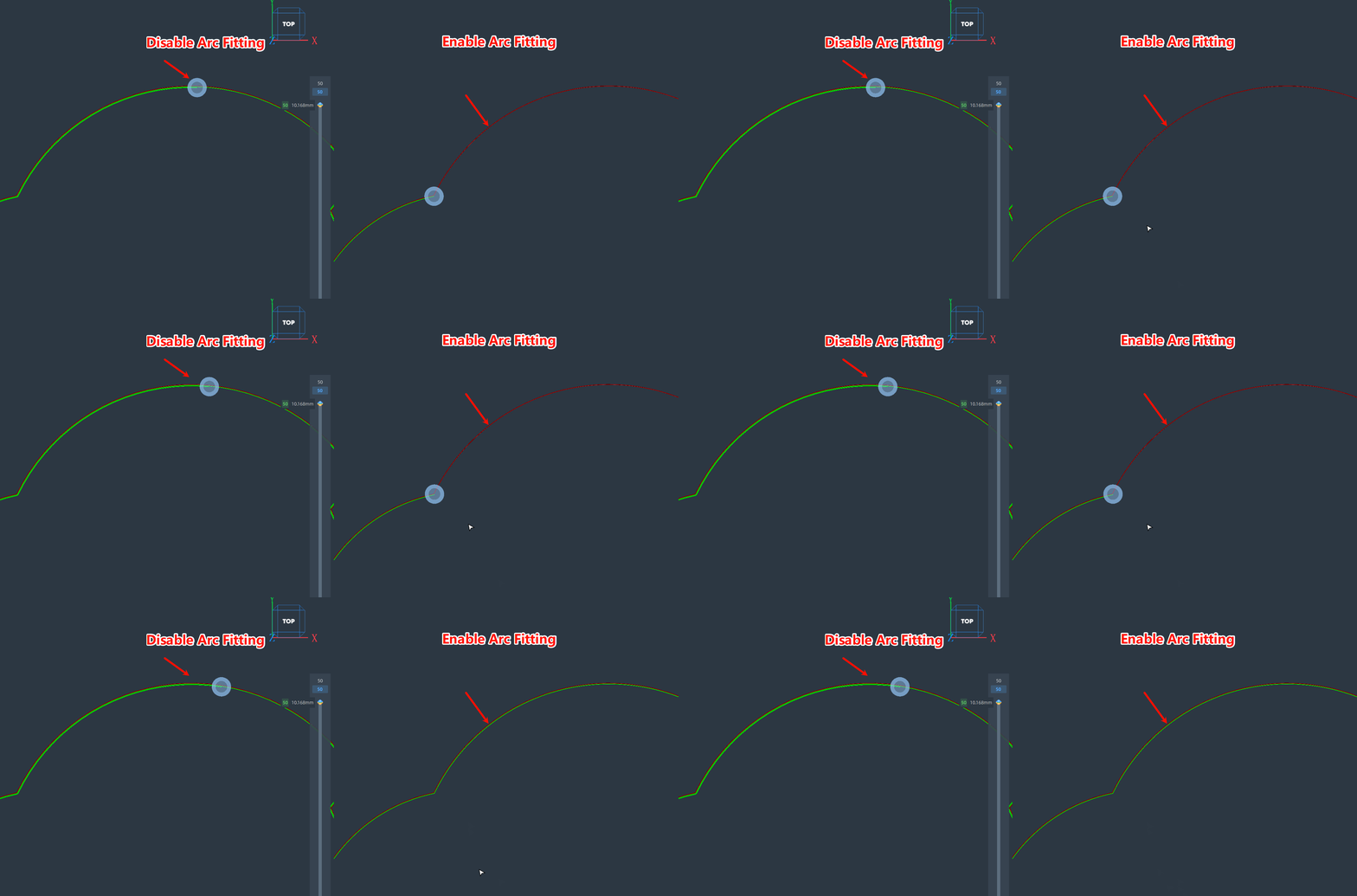
- Enable Arc Fitting
When arc fitting is enabled, arc movements in Gcode use G2 or G3 commands instead of multiple small line segments.
- Maximum Arc Path Deviation
The maximum deviation of the arc path from the original path. The smaller the deviation, the closer the fitted arc is to the original path.
- Maximum Arc Path Length Tolerance
The maximum difference between the fitted arc path and the original path. The smaller the percentage, the smaller the difference between the fitted arc and the original path.
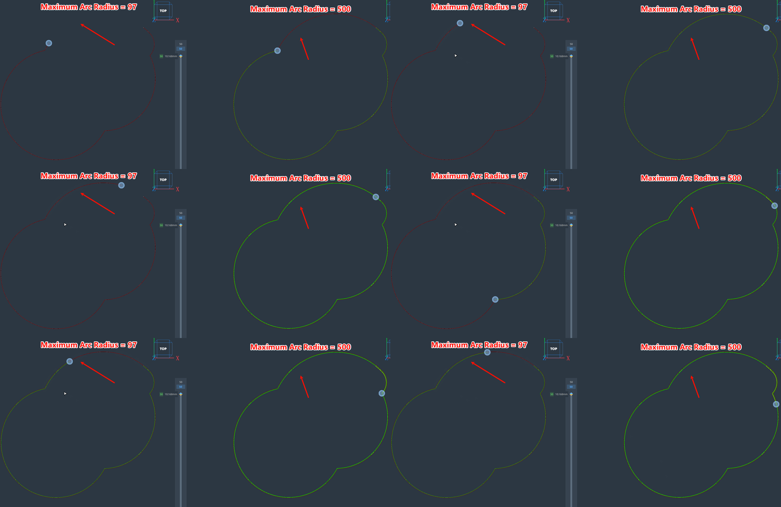
- Maximum Arc Radius
The maximum radius of the fitted arc. The larger the radius, the closer the arc is to a straight line.
¶ Small features
In 3D printing, small features refer to the fine details or structures included in the printed object, such as thin pillars, thin walls, intricate textures, or small holes. These small features impose higher demands on printing settings and the precision of the printer. Proper handling of small features can ensure the aesthetic and functional quality of the printed object.
¶ parameter setting
| parameters name | parameters meaning | parameter adjustment impact illustration | |
|---|---|---|---|
| 1 | Small Feature Maximum Length | Feature outlines shorter than this length will be printed using Small Feature Speed. |
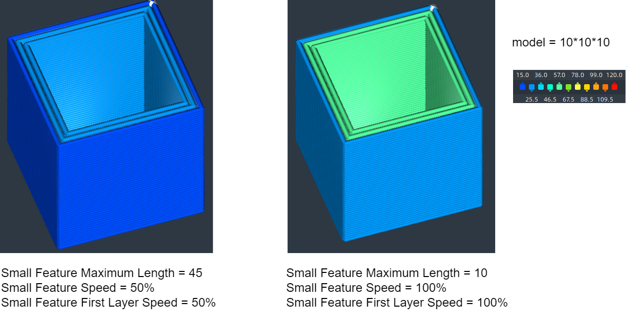 |
| 2 | Small Feature Speed | Small features will be printed at a reduced speed, which can enhance adhesion and precision. | |
| 3 | Small Feature First Layer Speed | Small features on the initial layer will be printed at a reduced speed, which can enhance adhesion and precision. |
¶ Travel move
¶ Key Considerations for Travel
Stringing and Oozing:
- Without proper retraction, the print head can leave strings or blobs of material during travel moves, affecting the surface quality of the print.
Print Time:
- Optimizing travel paths can reduce the time the print head spends moving without extruding, thereby increasing overall print efficiency.
Collisions and Vibrations:
- Avoiding obstacles in the travel path can reduce the risk of the print head colliding with already printed parts, which can cause vibrations or damage.
¶ parameter setting
| parameters name | parameter value | parameter meaning | parameter adjustment impact illustration | |
|---|---|---|---|---|
| 1 | Combing Mode |
off AII Not on Outer Surface Not in Skin Within Infill |
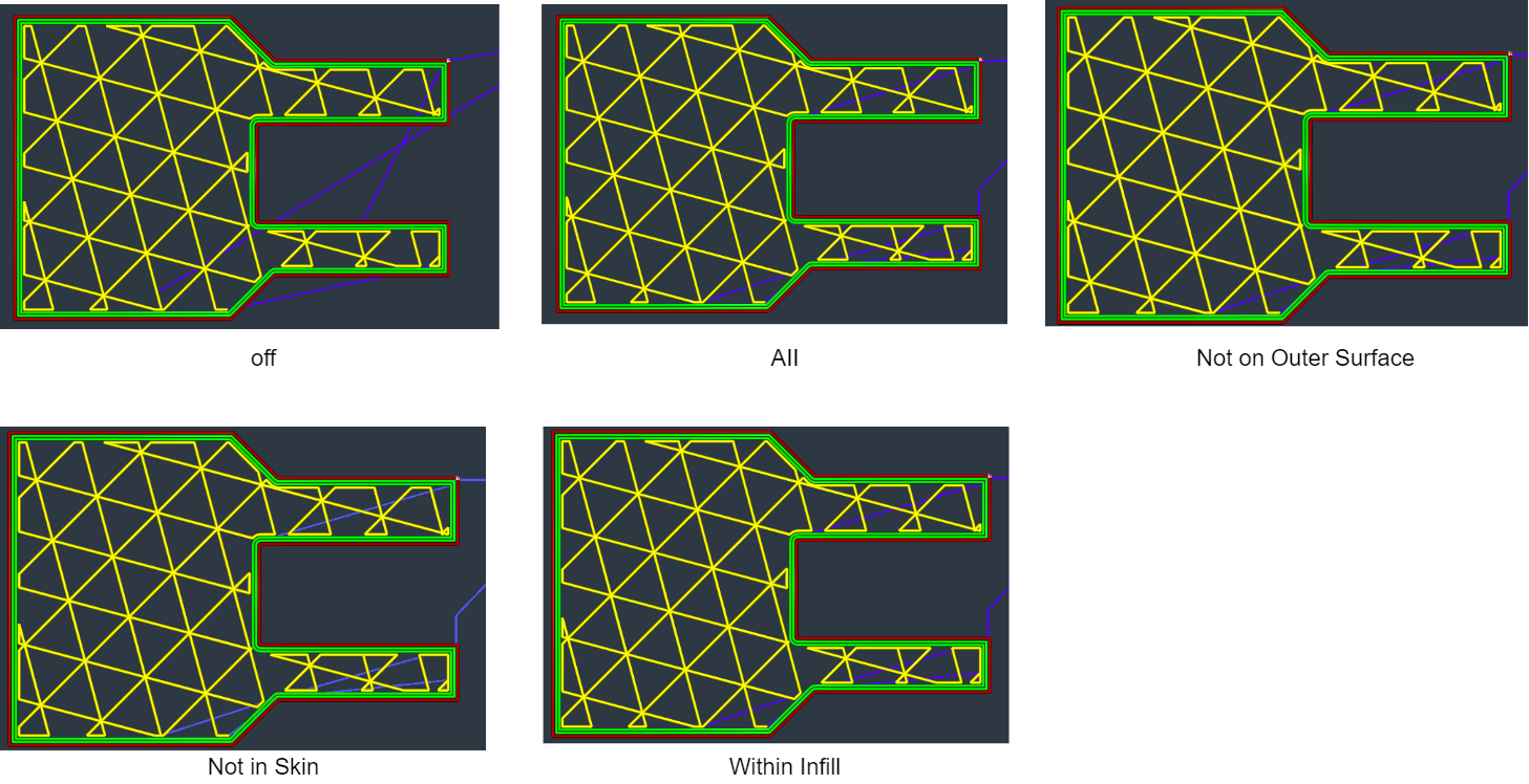
Combing keeps the nozzle within printed areas, reducing retractions and allowing for longer travel moves. If combing is off, retractions occur and the nozzle moves straight to the next point. Combing can also be limited to infill only, avoiding top/bottom skin areas. |
 |
| 2 | Retract Before Outer Wall | Retract when starting an outer wall. | ||
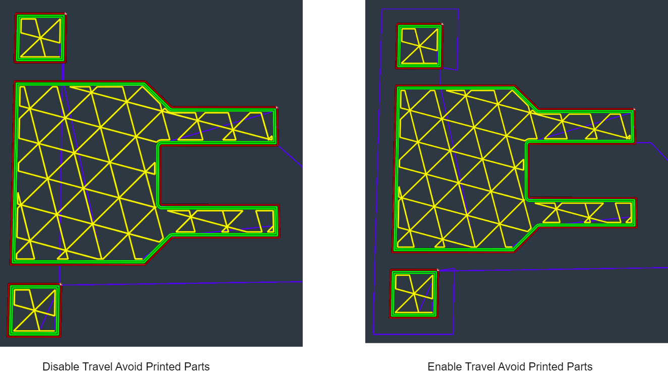
| 3 | Travel Avoid Printed Parts | The nozzle avoids printed parts when combing is enabled. |
 |
|
| 4 | Travel Avoid Distance | The nozzle's distance from printed parts during travel moves. | ||
| 5 | Layer Start X | The X coordinate for finding the part to print each layer. | ||
| 6 | Layer Start Y | The Y coordinate for finding the part to print each layer. | ||
| 7 | Maximum Comb Distance With No Retract | When greater than zero, combing travel moves that are longer than this distance will use retraction. If set to zero, there is no maximum and combing moves will not use retraction. |
¶ Z Hop
Z-Hop during retraction is a feature in many 3D printing slicer software that lifts the print head vertically along the Z-axis during a travel move when the filament is retracted. This technique helps avoid collisions with already printed areas, thereby preventing damage to the print and reducing the risk of stringing and oozing.
| parameters name | parameters meaning | parameter adjustment impact illustration | |
|---|---|---|---|
| 1 | Z Hop When Retracted | When retracting, the build plate is lowered to avoid nozzle collisions and prevent prints from being knocked off |
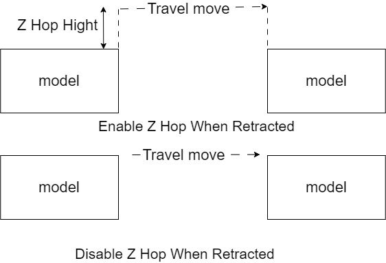 |
| 2 | Z Hop Hight | The vertical displacement during the execution of a Z Hop. | |
| 3 | Z Hop Only Over Printed Parts | Z Hop only when necessary. | |
| 4 | Z Hop After Extruder Switch | After switching extruders, the build plate is lowered to prevent oozed material from being left on the printed part. |
¶ Mesh fix
| parameters name | parameters meaning | |
|---|---|---|
| 1 | Delete Mesh Overlap | Delete one of the mesh intersections to prevent extruding twice on parts. |
| 2 | Alternate Mesh Deletion | When it is chosen to delete one of the mesh intersections, the meshes are alternatively removed to print layer by layer. |