¶ profile override
¶ Model parameters
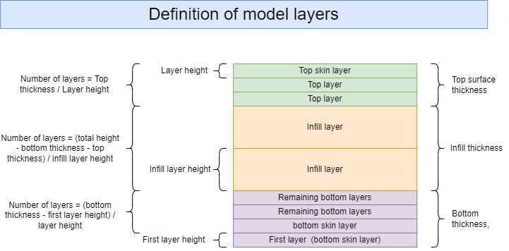
¶ The bottom layers of the Model
¶ First( initial )Layer of the Model
Parameter name |
Parameter meaning |
The impact of parameter adjustments on the NEO |
|
|---|---|---|---|
| 1 | First( initial )Layer line width | Initial Layer (First Layer) Line Width Print Enlargement Factor for All Objects: This setting applies to the line widths of inner walls, outer walls, infill, and skin, enhancing model adhesion to the build plate by increasing the proportion. | 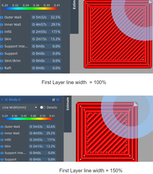 |
| 2 | Bottom Skin Inner Wall Line Width | The print width of the inner wall of the skin layer on the bottom surface of the model. | |
| 3 | Bottom Skin Outer Wall Line Width | The print width of the outer wall of the skin layer on the bottom surface of the model. | |
| 4 | Bottom Skin Infill Line Width | The print width of the skin layer filling on the bottom surface of the model. | |
| 5 | First( initial ) Layer Bottom Pattern | The options for the initial layer filling pattern of the model's skin, including concentric circles, straight lines, zigzags, and more. |  |
| 6 | Bottom Skin Line Directions | The integer line direction array to be used when using a straight or zigzag pattern for the top/bottom layer. As the layers progress, the angles listed in the array are used in sequence, and when the end of the list is reached, it starts again from the first angle. The list items are separated by commas and the entire list is enclosed in square brackets. An empty list, [ ], means using the traditional default angles (45 degrees and 135 degrees). For example, [35, 45, 55, 65] will cycle through 35, 45, 55, and 65 as the angles for every four layers. | |
| 7 | First( initial ) Layer Height | The initial layer height of the model, where a higher layer height makes it easier for the model to adhere to the printer's build plate platform. |
¶ Control parameters for the bottom surface skin layer of the model
Parameter name |
Parameter meaning |
The impact of parameter adjustments on the NEO |
|
|---|---|---|---|
| 1 | Bottom Skin Layers | The number of layers for the bottom layer skin. | |
| 2 | Bottom Skin Inner Wall Line Width | The print width of the inner wall of the skin layer on the bottom surface of the model. | |
| 3 | Bottom Skin Outer Wall Line Width | The print width of the outer wall of the skin layer on the bottom surface of the model. | |
| 4 | Bottom Skin Infill Line Width | The print width of the skin layer filling on the bottom surface of the model. | |
| 5 | Bottom Skin Pattern | The options for the bottom layer skin pattern of the model, which include concentric circles, straight lines, zigzags, and more. |  |
| 6 | Bottom Skin Line Directions | The integer line direction array to be used when using a straight or zigzag pattern for the top/bottom layer. As the layers progress, the angles listed in the array are used in sequence, and when the end of the list is reached, it starts again from the first angle. The list items are separated by commas and the entire list is enclosed in square brackets. An empty list, [ ], means using the traditional default angles (45 degrees and 135 degrees). For example, [35, 45, 55, 65] will cycle through 35, 45, 55, and 65 as the angles for every four layers. | |
| 7 | Bottom Skin Removal Width | The maximum width of the skin area to be removed, areas smaller than this value will not be printed. This helps to limit the time and material spent on printing the top/bottom layer skin on inclined surfaces of the model. This parameter is used to reduce the contact area between the solid bottom of the model and the outer edges, to improve the appearance quality of the bottom layer and increase the printing success rate. | |
| 8 | Bottom Skin Expand Distance | Referring to the distance between the skin and the infill, a larger value allows the skin to adhere better to the infill pattern and improves the adhesion of walls on adjacent layers to the skin. However, this results in increased material usage. |  |
| 9 | Maximum Expand Skin Angle | If the angle of the top or bottom surface of the model exceeds this setting, the skin of the top/bottom surface will not be expanded. This prevents the expansion of narrow skin areas when the model surface approaches a vertical slope. 0° angle is horizontal, while 90° angle is vertical. | |
| 10 | Minimum Expand Skin width | Skin areas narrower than the set parameter will not be expanded. This prevents the expansion of narrow surface areas when the model has a nearly vertical slope. | |
| 11 | Monotonic Top/Bottom Order | After enabling this feature, the bottom surface lines will be printed in sequential order, ensuring they are always parallel to adjacent lines and progress in one direction. This may increase printing time, but it will result in a more consistent appearance of the plane. |  |
| 12 | layer height | layer height |
¶ Parameters for other layers on the bottom surface of the model
Parameter name |
Parameter meaning |
The impact of parameter adjustments on the NEO |
|
|---|---|---|---|
| 1 | Bottom Line Width | Print line width for the fill on the model's bottom surface. | |
| 2 | Outer Wall Line Width | Printing line width for the outer walls of the model. By reducing this value, higher precision details can be achieved in the print. | |
| 3 | Inner Wall(s) Line Width | The printing width of the inner walls of the model. | |
| 4 | Bottom Thickness | The bottom thickness of the model, which determines the number of layers in the bottom surface. The bottom thickness is dependent on both the bottom layer height and layer height. | |
| 5 | Bottom Layers | The number of layers in the bottom, including the bottom skin layers and initial layers. | |
| 6 | Bottom Pattern | The options for the bottom layer pattern of the model, which include concentric circles, straight lines, zigzags, and more. |  |
| 7 | Bottom Line Directions | The integer line direction array to be used when using a straight or zigzag pattern for the top/bottom layer. As the layers progress, the angles listed in the array are used in sequence, and when the end of the list is reached, it starts again from the first angle. The list items are separated by commas and the entire list is enclosed in square brackets. An empty list, [ ], means using the traditional default angles (45 degrees and 135 degrees). For example, [35, 45, 55, 65] will cycle through 35, 45, 55, and 65 as the angles for every four layers. | |
| 8 | Overlap(mm) | The overlap amount (mm) between the bottom infill skin and the walls. A slight overlap ensures a tight connection between the walls and the infill skin. | |
| 9 | Skin Bottom Overlap (%) | The percentage of overlap between the bottom skin and the inner wall layers in relation to the skin line width. A slight overlap ensures a tight connection between the walls and the skin. | |
| 10 | Extra Skin Wall Count | Replace the outermost layer of the top/bottom infill with several concentric lines as additional skin walls. Using one or two lines can improve the top surface that starts with the infill material. | |
| 11 | layer height | layer height | |
| 12 | Monotonic Top/Bottom Order | After enabling this feature, the bottom surface lines will be printed in sequential order, ensuring they are always parallel to adjacent lines and progress in one direction. This may increase printing time, but it will result in a more consistent appearance of the plane. | |
| 13 | Ignore Small Z Gaps | This setting allows users to define whether to fill solid skin layers between different heights (in the Z-axis direction) of the model. When this option is enabled, the slicing software will not generate skin layers in the specified Z-axis gaps, creating voids. | 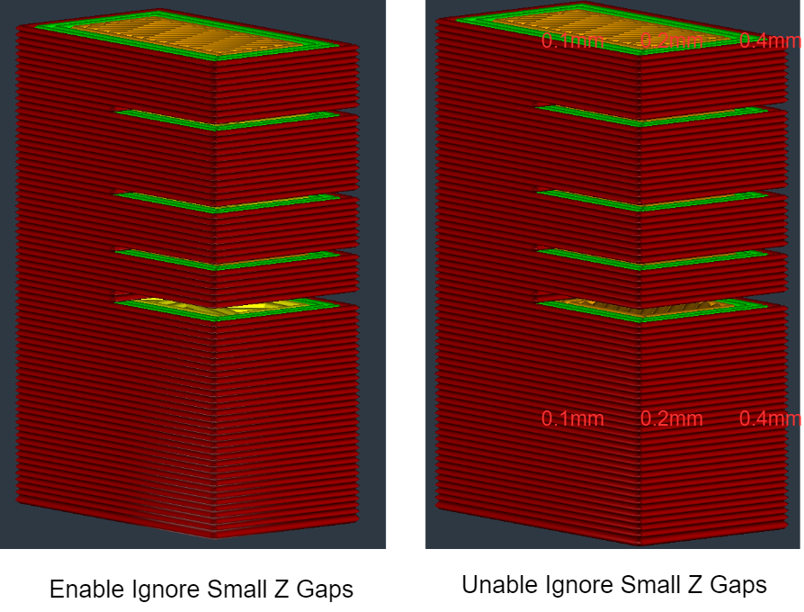 |
¶ Top surface parameters for the model
¶ Parameters of other layers on the top surface of the model
Parameter name |
Parameter meaning |
The impact of parameter adjustments on the NEO |
|
|---|---|---|---|
| 1 | Top Line Width | Print line width for the fill on the model's Top surface. | |
| 2 | Outer Wall Line Width | Printing line width for the outer walls of the model. By reducing this value, higher precision details can be achieved in the print. | |
| 3 | Inner Wall(s) Line Width | The printing width of the inner walls of the model. | |
| 4 | Top Thickness | Model's top thickness, along with the layer height, determines the number of top layers. | |
| 5 | Top Layers | The number of top layers in the model is calculated by rounding the value obtained from dividing the top thickness by the layer height to the nearest whole number. | |
| 6 | Top Pattern | The options for the Top layer pattern of the model, which include concentric circles, straight lines, zigzags, and more. |  |
| 7 | Top Line Directions | The integer line direction array to be used when using a straight or zigzag pattern for the top/bottom layer. As the layers progress, the angles listed in the array are used in sequence, and when the end of the list is reached, it starts again from the first angle. The list items are separated by commas and the entire list is enclosed in square brackets. An empty list, [ ], means using the traditional default angles (45 degrees and 135 degrees). For example, [35, 45, 55, 65] will cycle through 35, 45, 55, and 65 as the angles for every four layers. | |
| 8 | Overlap(mm) | The overlap amount (mm) between the Top infill skin and the walls. A slight overlap ensures a tight connection between the walls and the infill skin. | |
| 9 | Skin Top Overlap (%) | The percentage of overlap between the Top skin and the inner wall layers in relation to the skin line width. A slight overlap ensures a tight connection between the walls and the skin. | |
| 10 | Extra Skin Wall Count | Replace the outermost layer of the top/bottom infill with several concentric lines as additional skin walls. Using one or two lines can improve the top surface that starts with the infill material. | |
| 11 | Layer Height | layer height | |
| 12 | Monotonic Top/Bottom Order | After enabling this feature, the bottom surface lines will be printed in sequential order, ensuring they are always parallel to adjacent lines and progress in one direction. This may increase printing time, but it will result in a more consistent appearance of the plane. | |
| 13 | Ignore Small Z Gaps | This setting allows users to define whether to fill solid skin layers between different heights (in the Z-axis direction) of the model. When this option is enabled, the slicing software will not generate skin layers in the specified Z-axis gaps, creating voids. |
¶ Parameters of the top skin layer of the model.
Parameter name |
Parameter meaning |
The impact of parameter adjustments on the NEO |
|
|---|---|---|---|
| 1 | Top Skin Layers | The number of top skin layers in the model. | |
| 2 | Top Skin Inner Wall Line Width | The width of the inner wall of the top skin layer in the model. | |
| 3 | Top Skin Outer Wall Line Width | The width of the outer surface of the top skin layer in the model. | |
| 4 | Top Skin Infill Line Width | The width of the fill in the top skin layer of the model. | |
| 5 | Top Skin Pattern | The available options for the fill style in the top skin layer of the model include concentric circles, straight lines, zigzag patterns, and more. |  |
| 6 | Top Skin Line Directions | The integer line direction array to be used when using a straight or zigzag pattern for the top/bottom layer. As the layers progress, the angles listed in the array are used in sequence, and when the end of the list is reached, it starts again from the first angle. The list items are separated by commas and the entire list is enclosed in square brackets. An empty list, [ ], means using the traditional default angles (45 degrees and 135 degrees). For example, [35, 45, 55, 65] will cycle through 35, 45, 55, and 65 as the angles for every four layers. | |
| 7 | Top Skin Removal Width | The maximum width of the skin area to be removed, areas smaller than this value will not be printed. This helps to limit the time and material spent on printing the top/bottom layer skin on inclined surfaces of the model. This parameter is used to reduce the contact area between the solid bottom of the model and the outer edges, to improve the appearance quality of the bottom layer and increase the printing success rate. | 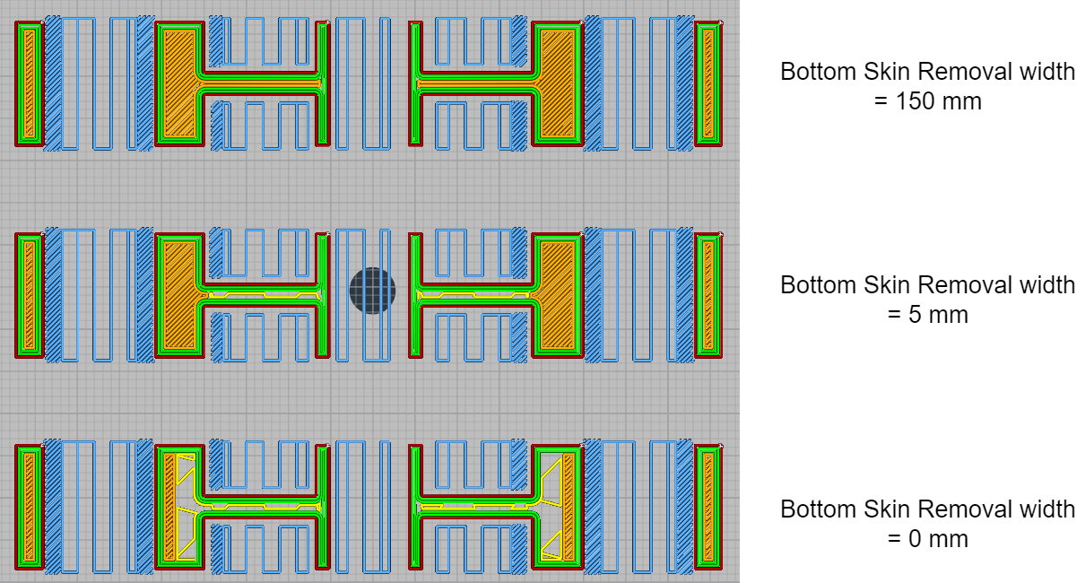 |
| 8 | Top Skin Expand Distance | Referring to the distance between the skin and the infill, a larger value allows the skin to adhere better to the infill pattern and improves the adhesion of walls on adjacent layers to the skin. However, this results in increased material usage. |  |
| 9 | Maximum Expand Skin Angle | If the angle of the top or bottom surface of the model exceeds this setting, the skin of the top/bottom surface will not be expanded. This prevents the expansion of narrow skin areas when the model surface approaches a vertical slope. 0° angle is horizontal, while 90° angle is vertical. |  |
| 10 | Minimum Expand Skin width | Skin areas narrower than the set parameter will not be expanded. This prevents the expansion of narrow surface areas when the model has a nearly vertical slope. | |
| 11 | Monotonic Top/Bottom Order | After enabling this feature, the bottom surface lines will be printed in sequential order, ensuring they are always parallel to adjacent lines and progress in one direction. This may increase printing time, but it will result in a more consistent appearance of the plane. | |
| 12 | layer height | layer height |
¶ Wall parameters
¶ Parameters of the vertical wall
Parameter name |
Parameter meaning |
The impact of parameter adjustments on the NEO |
|
|---|---|---|---|
| 1 | Wall Thickness | Horizontal wall thickness. This value, divided by the line width, determines the number of walls on the surface. | |
| 2 | Wall Line Count | Number of walls. When calculated based on wall thickness, this value is rounded to the nearest integer. | |
| 3 | Topmost Skin wall Count | Number of Roof skin loops in the model's top surface. | |
| 4 | Top Skin Wall Count | Number of top skin loops above the bottom surface of the model. | |
| 5 | Most Bottom Skin Wall Count | Number of Floor skin loops in the model's bottom surface. | |
| 6 | Bottom Skin Wall Count | Number of bottom skin loops above the bottom surface of the model. | |
| 7 | Enable Print Thin Walls | Enable thin wall printing. |  |
| 8 | Minimum Feature Size | Minimum wall thickness for thin wall features. Model features below this value will not be printed, while features larger than the minimum size will be increased to the minimum line width. | |
| 9 | Minimum Thin Wall Line Width | The minimum thin wall line width will replace the wall thickness of the model's thin wall features (based on the minimum feature size). If the minimum feature is thinner than this minimum line width setting, the thin wall will be thickened to be printed at the minimum line width. | |
| 10 | Horizontal Expand | The offset value for all polygons in each layer. Positive values can compensate for oversized holes, while negative values can compensate for undersized holes. | 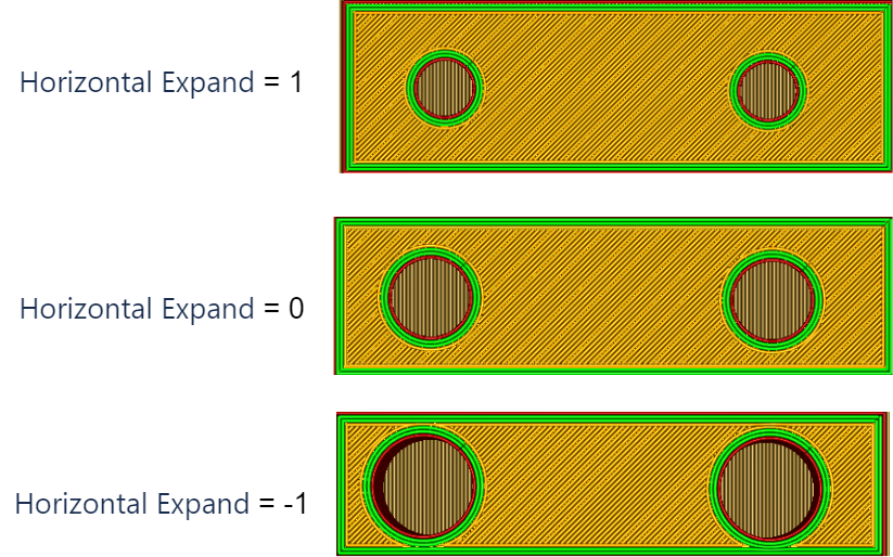 |
| 11 | First Layer Horiz Expand | The offset value for all polygons in the first layer. Negative values can compensate for the extrusion in the first layer, commonly referred to as "elephant's foot." | |
| 12 | Horizontal Size Compensation Type | Size Compensation Ratio Compensation |
|
| 13 | Inner Hole Compensation | The size offset for all the holes in each layer. | |
| 14 | Outer Profile Compensation | The size offset applies to all outer contours in each layer. |
¶ Parameters of the Overhanging wall
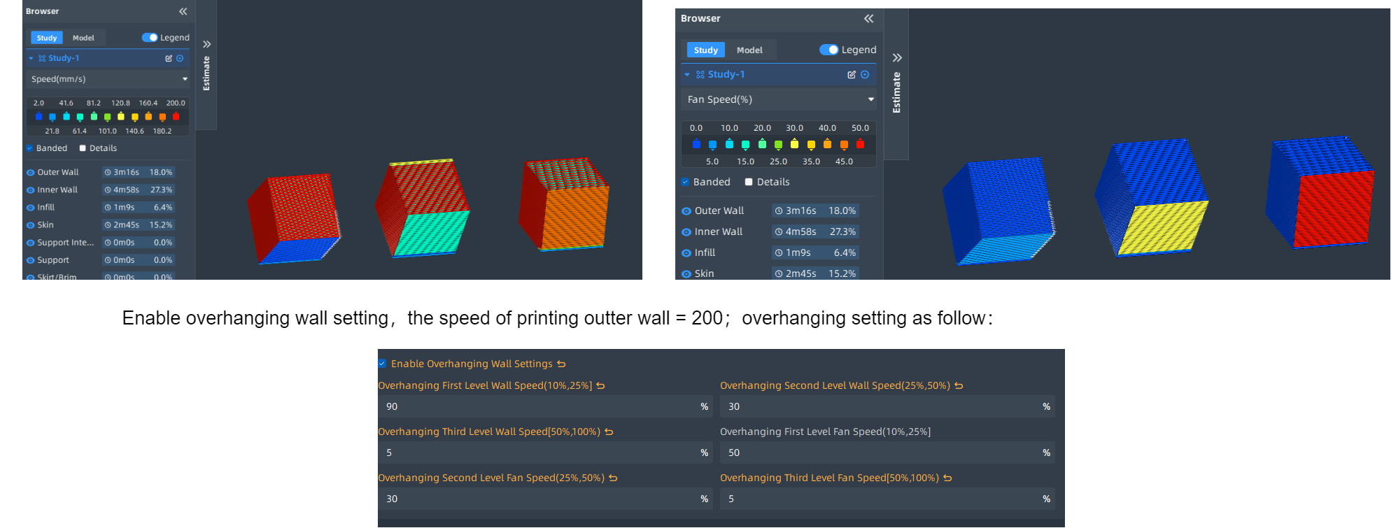
Overhangs in 3D printing refer to the parts or structures that do not have direct support relative to the bottom layer. These parts typically hang at a certain angle above the main body of the printed object. During the printing process, special attention needs to be paid to overhangs because the lack of support can lead to printing failures or quality issues.
Parameter name |
Parameter meaning |
The impact of parameter adjustments on the NEO |
|---|---|---|
| Enable Overhanging Wall Settings | Enable overhang detection and modify print speed, flow rate, and fan settings when printing overhangs. | |
| Overhanging First Level Wall Speed(10%,25%] | The overhang walls will be printed at a speed obtained by multiplying the normal print speed by the percentage set. | |
| Overhanging Second Level Wall Speed(25%,50%) | The overhang walls will be printed at a speed obtained by multiplying the normal print speed by the percentage set. | |
| Overhanging Third Level Wall Speed[50%,100%) | The overhang walls will be printed at a speed obtained by multiplying the normal print speed by the percentage set. | |
| Overhanging First Level Fan Speed(10%,25%] | The fan speed percentage used when printing the first level of overhangs. | |
| Overhanging Second Level Fan Speed(25%,50%) | The fan speed percentage used when printing the second level of overhangs. | |
| Overhanging Third Level Fan Speed[50%,100%) | The fan speed percentage used when printing the third level of overhangs. |
¶ Parameters of infill
Parameter name |
Parameter meaning |
The impact of parameter adjustments on the NEO |
|
|---|---|---|---|
| 1 | Infill Pattern | The filling patterns of the infill material. Lines and zigzag patterns alternate direction on alternating layers to reduce material costs. Grid, triangle, hexagon, cube, octagon, quarter-cube, cross, and concentric circle patterns remain consistent on each layer. Cube, quarter-cube, and octagon infills vary with each layer to provide a more uniform distribution of strength in every direction. | 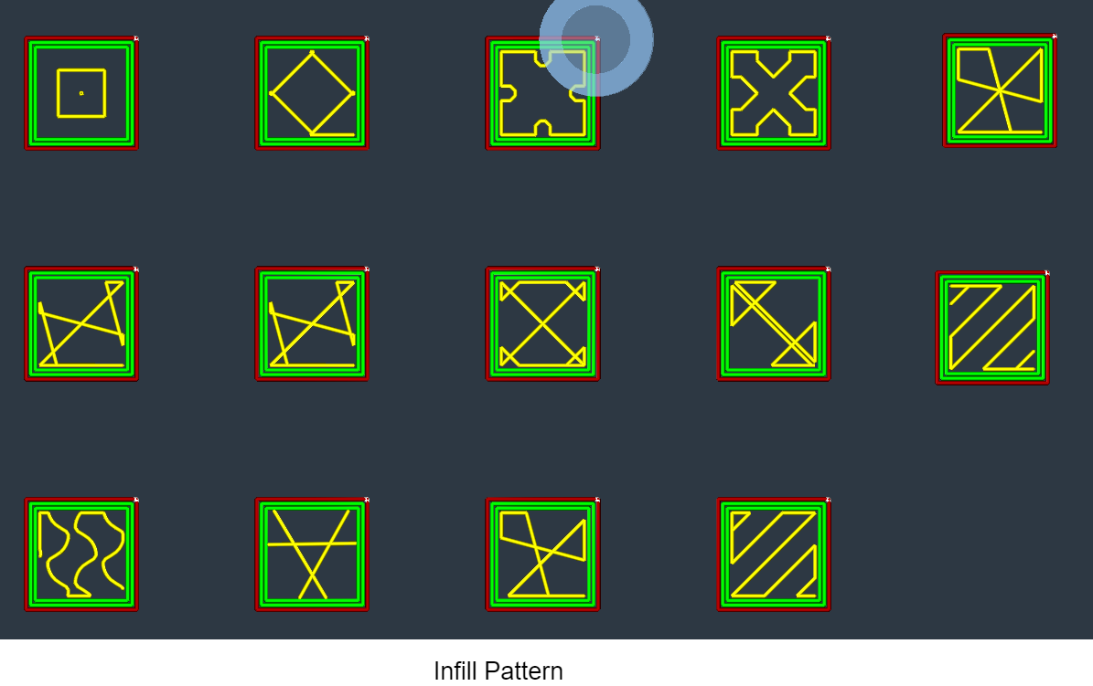 |
| 2 | Infill Before Walls | Printing the infill before the walls can result in a more precise wall surface, but may lead to poorer quality on overhangs. Printing the infill first can make the walls more sturdy, but the pattern of the infill may sometimes be visible through the wall surface. | |
| 3 | Infill Density | Adjust the infill density of the print. A higher infill density results in increased part strength, but also leads to longer print times. | 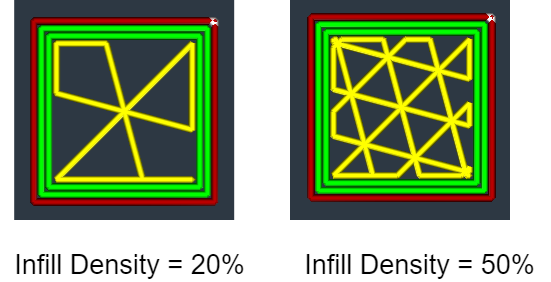 |
| 4 | Infill Line Distance | Adjust the spacing between the infill lines of the print. This setting is determined by the infill density and the infill line width. | |
| 5 | Infill Overlap(%) | The percentage of overlap between the infill lines and the walls, as a proportion of the infill line width. Slight overlap can ensure a strong connection between the walls and the infill. | 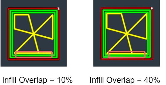 |
| 6 | Infill Overlap(mm) | The amount of overlap between the infill and the walls. Slight overlap can ensure a strong connection between the walls and the infill. | |
| 7 | Extra Infill wall Count | Add additional walls around the infill area. These walls can reduce the drooping of the top/bottom skin lines, meaning you can achieve the same quality with fewer top/bottom skin layers at the expense of some extra material. This feature can be combined with connected infill polygons, and if configured correctly, it can connect all infill to a single extrusion path without the need for travel or retraction. | 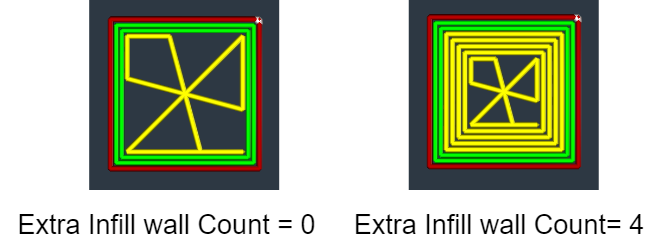 |
| 8 | Infill Line Direction | The integer line direction array to be used when using a straight or zigzag pattern for the top/bottom layer. As the layers progress, the angles listed in the array are used in sequence, and when the end of the list is reached, it starts again from the first angle. The list items are separated by commas and the entire list is enclosed in square brackets. An empty list, [ ], means using the traditional default angles (45 degrees and 135 degrees). For example, [35, 45, 55, 65] will cycle through 35, 45, 55, and 65 as the angles for every four layers. | |
| 9 | Infill x offset | Translate the infill pattern along the X-axis by a specific distance. | 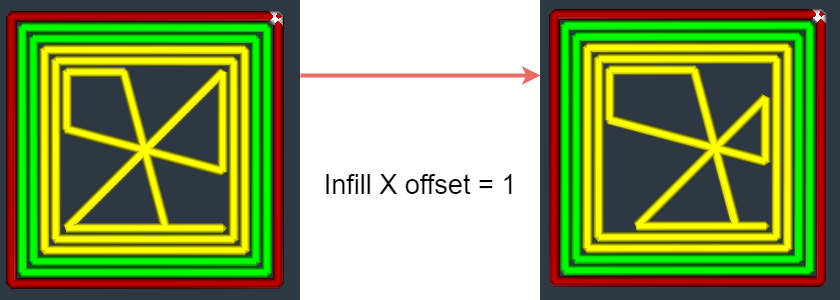 |
| 10 | Infill Y offset | Translate the infill pattern along the Y-axis by a specific distance. | 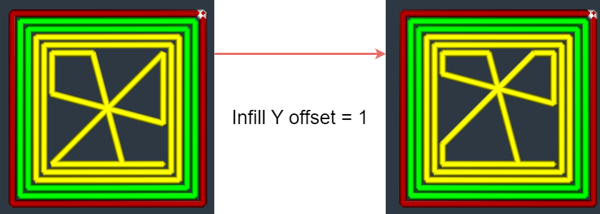 |
| 11 | Infill Line Multiplier | The number of segments each infill line is converted into. These additional lines do not intersect but rather avoid each other, making the infill stronger but increasing print time and material usage. | 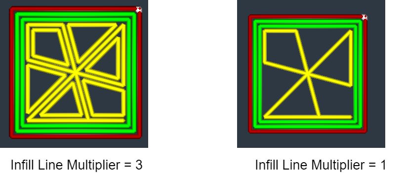 |
| 12 | Connect Infill Lines | Connect the infill pattern to the inner wall at the junction with a line that matches the shape of the inner wall. Enabling this setting can improve adhesion of the infill to the wall and reduce the impact of the infill on the quality of vertical surfaces. Disabling this setting will reduce material usage. | 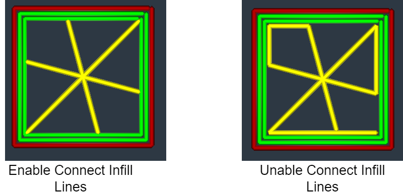 |
| 13 | Randomize Infill Start | Print the infill lines in a random order. This can prevent any specific area from becoming the strongest, but it will increase additional movement overhead. |