User Manual
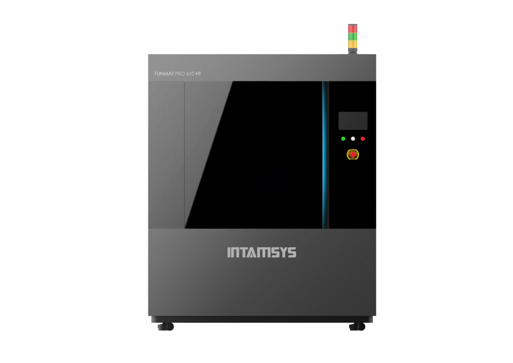
FUNMAT PRO 610HT
Large Scale∣High Temperature∣Industrial Production
¶ 1 Service and Support
This chapter provides information on the services and supports of FUNMAT PRO 610 HT industrial- grade 3D printer (hereinafter referred to as “printer”, “equipment” or “machine”), as well as safety information and safety label locations.
¶ 1.1 Service
Please contact INTAMSYS customer support for any problem not covered by this guide during your use of the printer.
| Region | Tel. | |
| Asia Pacific | Support_APAC@intamsys.com | +86-21-5846 5932 |
| Europe, Middle East and Africa | Support_EMEA@intamsys.com | +86-21-5846 5932 |
| North America / Latin America | Support_America@intamsys.com | +1-651-348-7309 |
¶ 1.2 Safety Information
The following basic safety tips are used to ensure installation, operation, and maintenance of INTAMSYS devices in safe way and should not be considered a comprehensive safety issue. The printer is a safe and reliable industrial-grade 3D equipment. The area around the printer must be checked for potential hazards before stating to use.
¶ 1.2.1 Hazard Classification
It is recommended by INTAMSYS that all services or operations should be executed by qualified personnel. All personnel operating the printer or near by the printer shall understand the meaning of following hazard classification used in this guide.

[High voltage warning] : The sign of high voltage indicates the existence of high voltage. Be sure to keep away from exposed circuits. It is suggested to take off all accessories.

[High temperature warning]:The warning indicates that the equipment is in high temperature. Take extra care when working close to heated components. Be sure to wear the safety gloves provided coming with the printer.
The printing head temperature in the printer can be up to 500℃ .
The chamber temperature in the printer can be up to 300℃ .

[Pinch warning]: The warning indicates that you may have a risk to pinch hand between two objects. There are one or multiple objects moving in your working area.
¶ 1.2.2 Potential Safety Hazard Area
The following components and areas have been highlighted as potential safety hazards. Failure to follow safety procedures correctly can cause system failures or reliability issues.
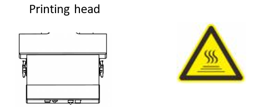
[High temperature Warning] Warning: When printing head is heated, safety gloves must be worn if maintenance of printing head or work in the chamber.
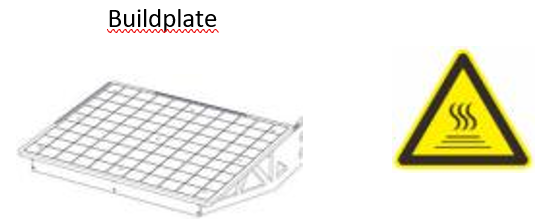
[High temperature Warning] Warning: During the heating of chamber, please wear safety gloves when removing the buildsheet or working in the chamber.
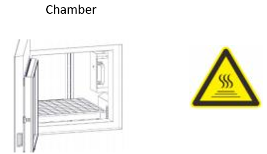
[High temperature Warning] Warning: When the chamber is heated, such as medium-low temperature, safety gloves must be worn when working in the chamber; when in high temperature, it is not recommended to work in the chamber.
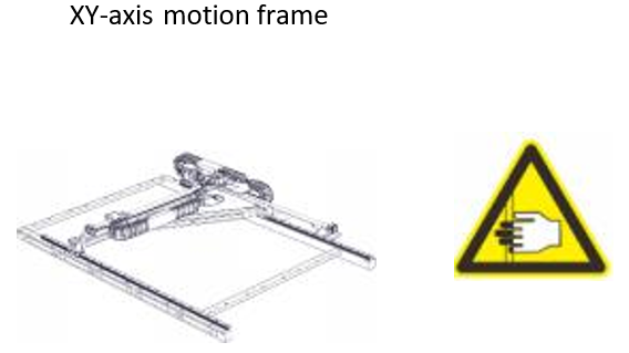
[Pinch warning] Warning: Do not wear ties, loose clothing or hanging accessories while working near moving components.
[Pinch warning] Warning: Do not click "HOME" when there is a model on the platform.
[Pinch warning] Warning: Please take extra care when overhauling this motion component.

[Pinch warning] Warning: Do not wear ties, loose clothing or hanging accessories while working near moving components.
[Anti-collision]: If there is a printed model on the platform, when the platform rises, pay attention to the height to prevent puncturing the organ type shield.
[Anti-collision]: If there is any object below the platform, when the platform falls, pay attention to the height to prevent deformation of drive rod parts and leveling failure due to collision with the platform.
¶ 1.2.3 Operating State
Turn the mode selector switch to AUTO or MANU by rotating the key.
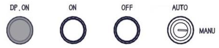
• AUTO mode: Start the safety control system. To open the front door and top cover, the following conditions must be met: When the motion mechanism stops moving and the chamber temperature is lower than 70℃℃, operate the screen to unlock the safety lock; after the front door and top cover are closed, press the white "DP.ON" button once to restore the power supply and start the AUTO mode.
Note: In the AUTO mode, the lock sensor is used to monitor the status of the chamber’s front door and top cover. For safety reasons, the chamber’s front door and top cover must be closed before the chamber is heated or XYZ motors start working. The electromagnetic lock ensures that the chamber’s front door and top cover are firmly closed during printer’s operation.
• MANU mode: Maintenance mode. In this mode, the front door or top cover can be opened by operation on the screen in any case, without being limited by the motion state and chamber temperature.
• Note: In this state, operations must be done by professionals with corresponding protective measures.
¶ 1.2.4 Environmental Requirement
• The printer is for indoor use only.
• Quality conditions with excessive solid particles (conductive or non-conductive) might cause damages to the equipment.
• The operating temperature of the system shall be between 15°C and 30°C (59°F to 86°F), and the relative humidity shall be between 30% and 70% (non-condensation).
• The system storage temperature shall be in the range of 0°C to 35°C (32°F to 95°F) and the relative humidity shall be in the range of 20% to 90% (non-condensation).
¶ 2 Setup and Installation
This chapter describes the basic setup and installation of FUNMAT PRO 610 HT.
¶ 2.1 General Information
¶ 2.1.1 Attached Tools
Please check the attached packing list (see appendix). These attached tools are common tools and spare parts for printer maintenance.
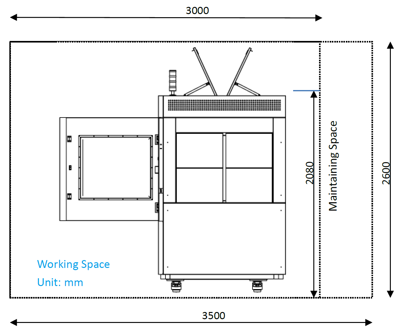
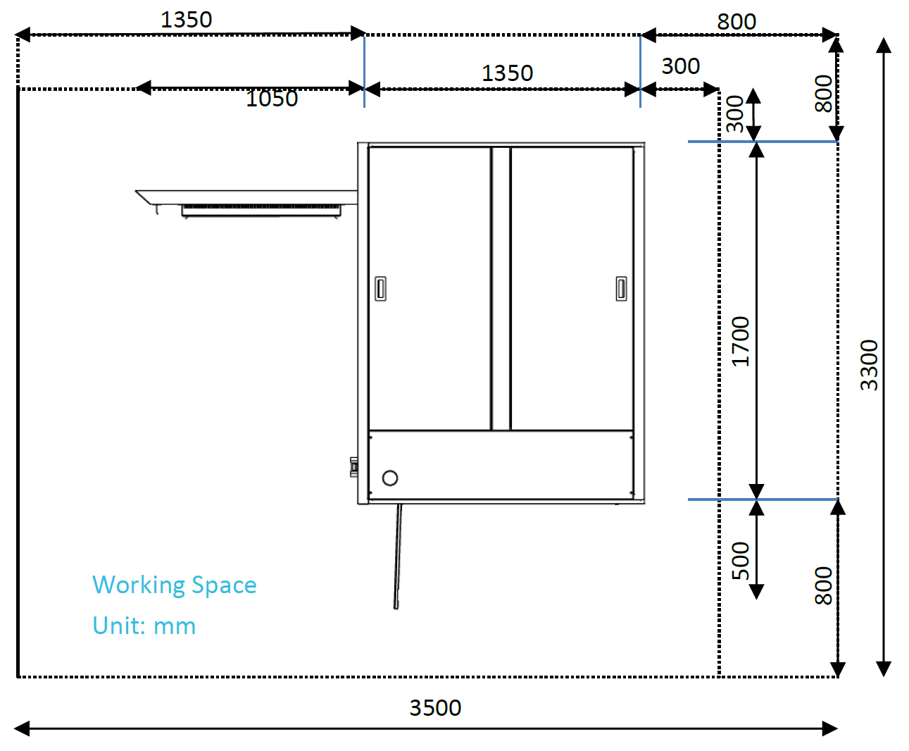
¶ 2.1.2 Working Space Requirements for Installation
Check installation site preparation guide to ensure efficient and safe preparation of relevant facilities to install the printer.
¶ 2.1.3 Inspection of the Printer Nameplate
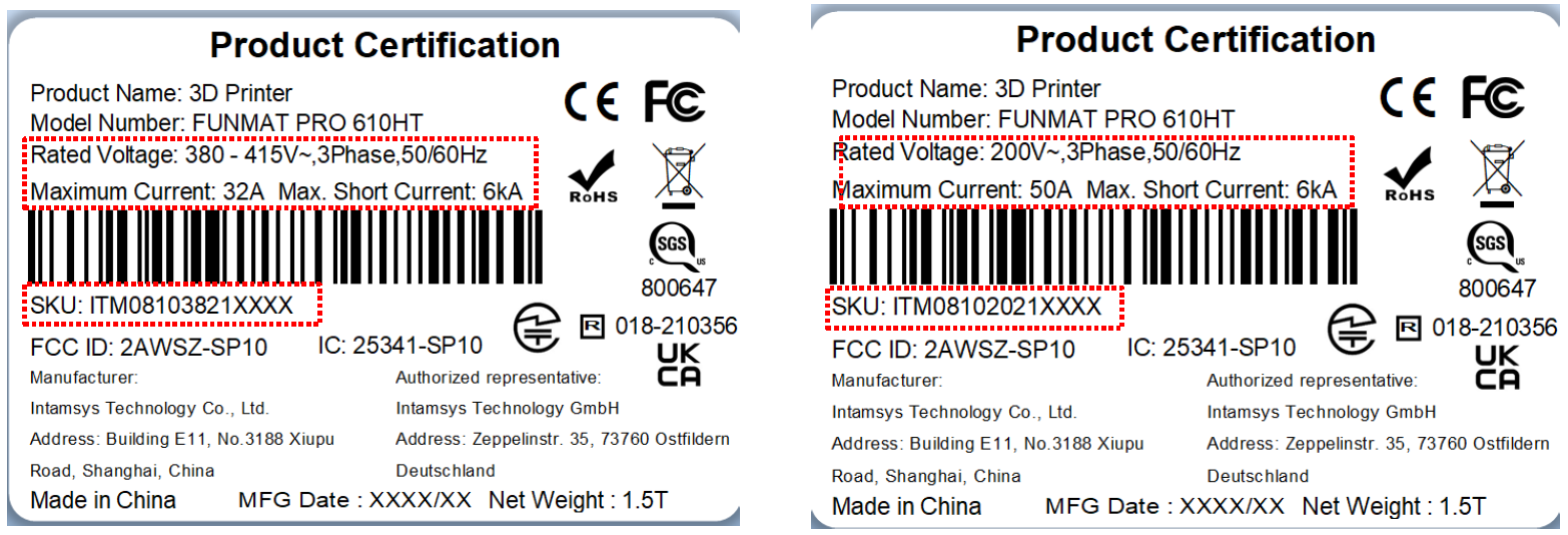
Identify your printer by below illustration.
Model mark: It lists the product name, printer model number and power requirements. This nameplate also lists the relevant certification information and INTAMSYS information.
Serial number: Please provide the serial number listed in the nameplate to the INTAMSYS authorized partner or INTAMSYS when requesting service, so that the service personnel can quickly identify your printer configuration.
¶ 2.2 Machine Preparation
¶ 2.2.1 Remove Package
Prepare the following unpacking tools: forklift, pallet jack (with a recommended bearing capacity of 3000 kg), electric hand drill with 8 mm sleeve (or open-end wrench), ladder, wallpaper knife, etc.
Such tools can be substituted as appropriate.
Step 1: Please remove the screws on the wooden box with a manual electric drill equipped with 8 mm sleeve. Remove all the boards and remove the tape, foam and packing film from the machine. Use the ladder when working at height.
Step 2: Use forklift (load capacity ≥2000Kg) to remove the equipment from the wooden pallet. It should be placed on the flat ground before the printer being moved to designated place. (Pay attention to the three-color lighthouse on the pallet).
Step 3: Use forklift to move the equipment to the factory and place it in the designated position.
Step 4: After determining the position, hold up the four legs and fix the equipment.
¶ 2.2.2 Equipment Reset
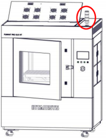
Step 1: Install the three-color lighthouse on the top right front of the printer with the help of a ladder. Before installation, plug the signal wires properly;
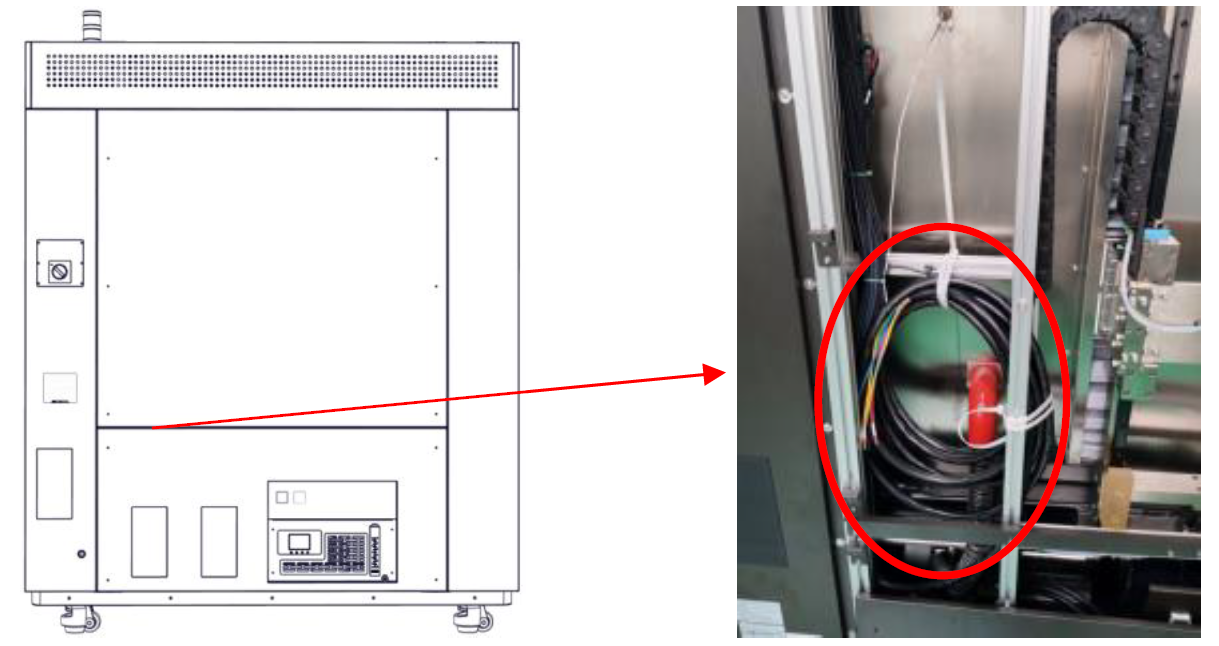
Step 2: Remove the two sheet metals on the back side of the equipment, and take out the power line;
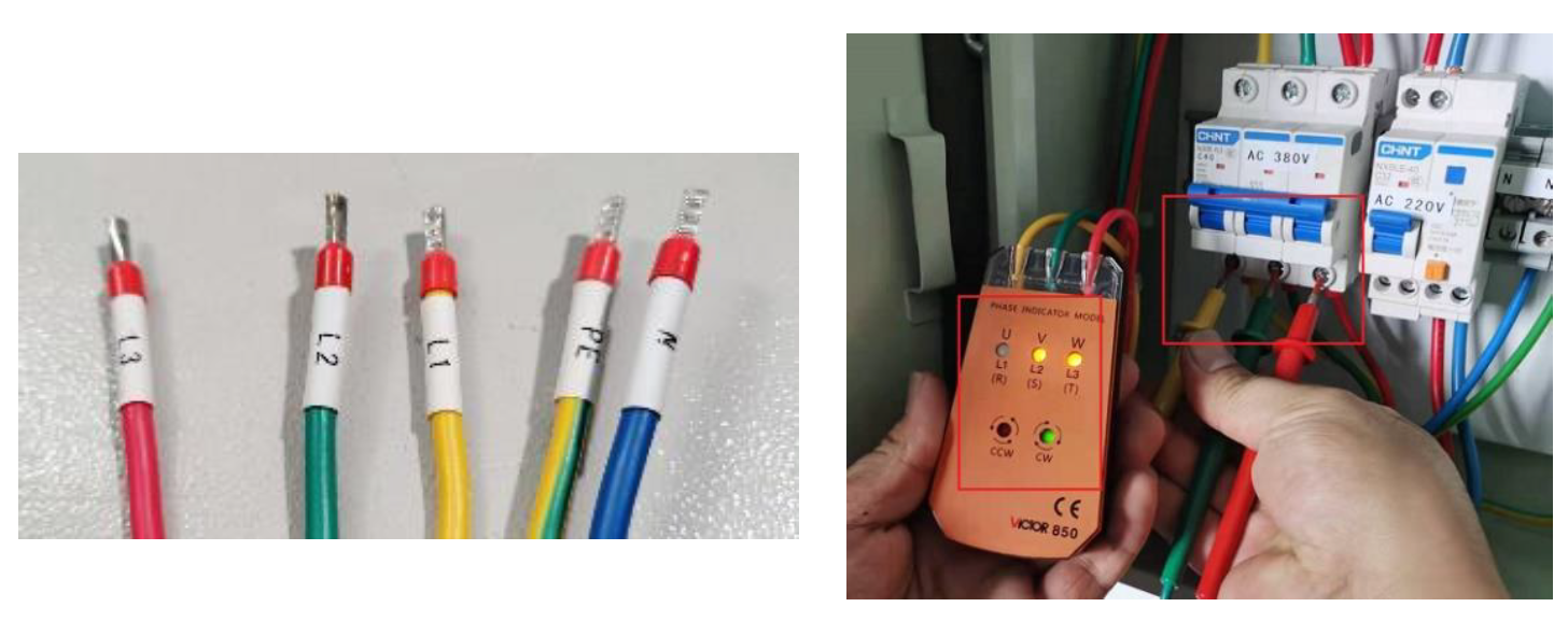
Step 3: Confirm the port number of each cable on the power line, and connect the power supply according to the sequence of cables. The electrician or professional shall measure the phase sequence of power supply with a three-phase AC phase meter to ensure correct wiring. Connect the specified pins in turn according to the input. If the CW light is green, the phase sequence is correct; otherwise, adjust the sequence of cables;
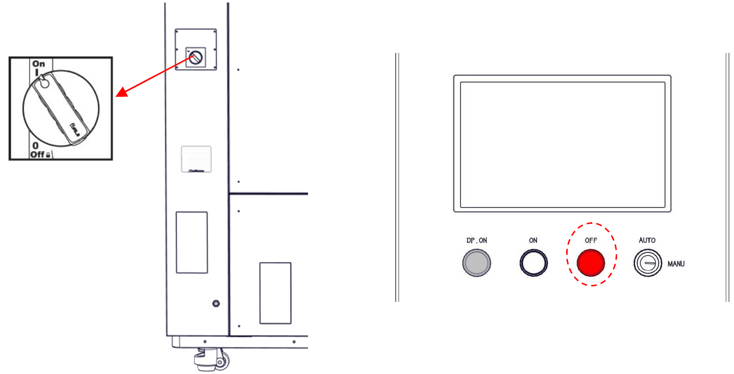
Step 4: Turn the knob on the right rear of the equipment to "ON" (make sure that the air switch on the right rear of the equipment is turned on) to power on the equipment, and the "OFF" button on the control panel lights up in red;
Step 5: Press the "ON" button on the control panel; the "ON" button lights up in green, the "OFF" button lights off, and the startup process starts. After the equipment is started, click the "Unlock" button on the screen to open the front door (Note: Do not reset the equipment, and the XY axis is locked at this time);
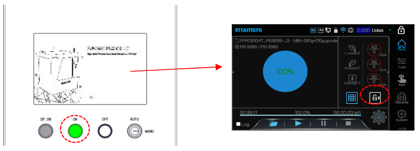
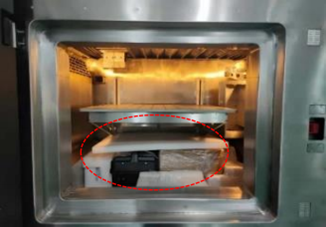
Step 6: Open the front door, take out the attached accessories (such as printing head cover, aggregate box, toolkit and printing plate), and make sure there is no debris in the chamber;
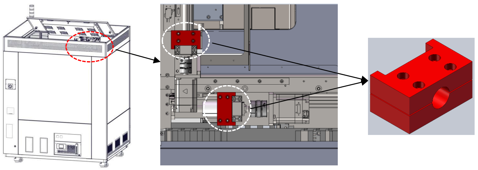
Step 7: Place the ladder on the left rear of the equipment, and open the rear top cover with the help of the ladder. There are red fixing blocks on the XY axis shaft screws near the motor to limit shaft screw rotation. Loosen the four M6 hexagon socket screws to remove the fixing blocks;
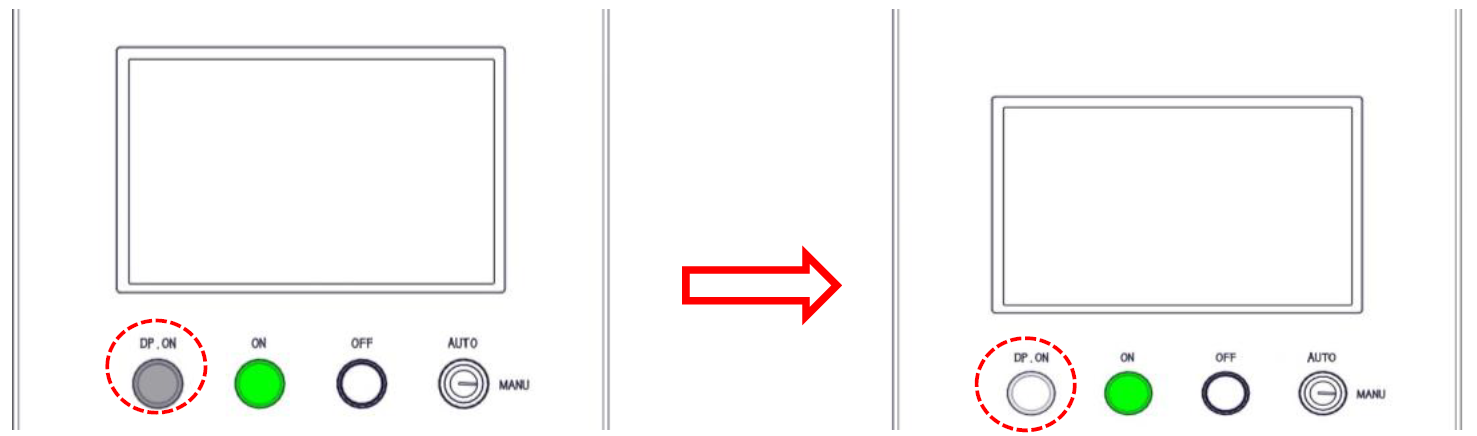
Step 8: Press the white "DP.ON" button to power on the XYZ axis. The button lights up in white;
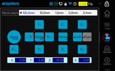
Step 9: Click the "Axis" icon to enter the "MANU" interface, and click the "HomeXY" icon to return to the XY origin;
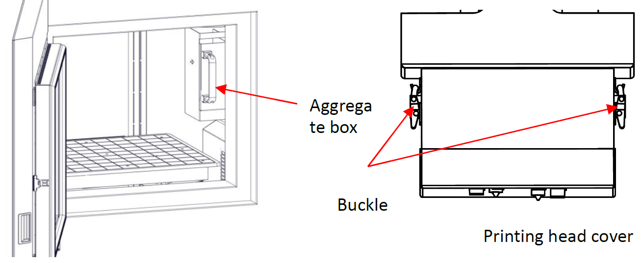
Step 10: Install the aggregate box and printing head cover. Pay attention to the location of printing head and air duct. After buckling, fasten the elastic buckles on both sides;
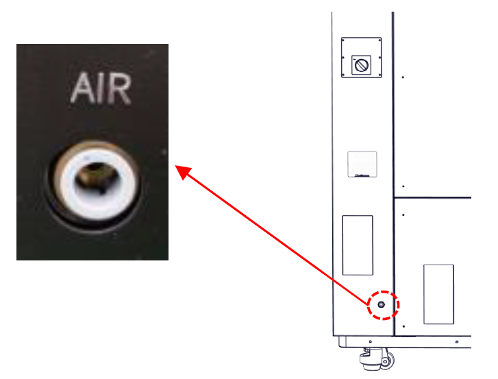
Step 11: Connect the compressed air source with a φ10 quick connector (Note: Make sure that the compressed air supplied is clean and dry);
Step 12: Add coolant for the equipment: Use a straight screwdriver to unscrew the cap at the coolant nozzle, insert the funnel, and fill coolant through the funnel.
¶ 2.2.3 Filling and Discharge of Coolant
Step 1: Use a straight screwdriver to unscrew the cap at the coolant nozzle (as shown in the figure below) and fill the tank through the funnel.
Step 2: Fill clean coolant through the funnel, and adding liquid must exceed the minimum liquid level line 0.35. In order to achieve a better effect of the chiller, it is recommended to make the liquid level as close to the highest liquid level line 1.0 as possible, with the maximum filling volume of about 1.8L.
Step 3: Reset the cap after filling coolant.
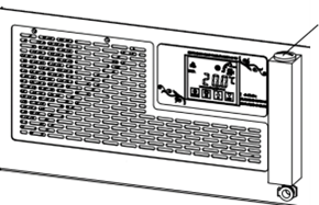
Note: When the machine is not used for a long time, please empty the water inside. The drain outlet is a quick female connector with a valve, which needs to be connected to the standard male connector (see the attached list) to complete the drainage operation. For other relevant information, see 7.4.3.
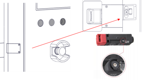
¶ 2.2.4 Unlocking of the Front Door When Powered-off
When the equipment is powered off, if the front door safety lock is locked, manually reset the safety lock.
Step 1: Remove the sheet metal at the position of the front door safety lock;
Step 2: Reset the mechanical lock function of the front door safety lock with a cross screwdriver or special tool, when the front door can be opened.
Step 3: After the door is opened, reset the safety lock and the protective sheet metal.
¶ 3 Printer Components
This chapter describes the FUNMAT PRO 610 HT system components to help users better understand how the printer works and understand the functions of each core component.
¶ 3.1 Printer Abstract
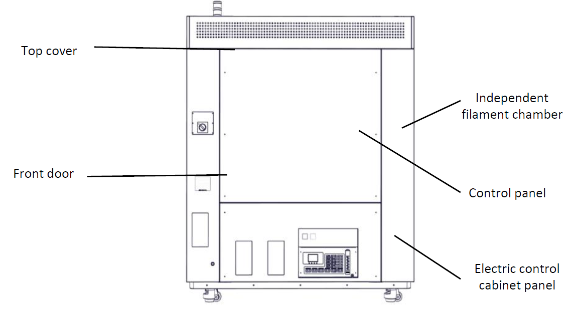
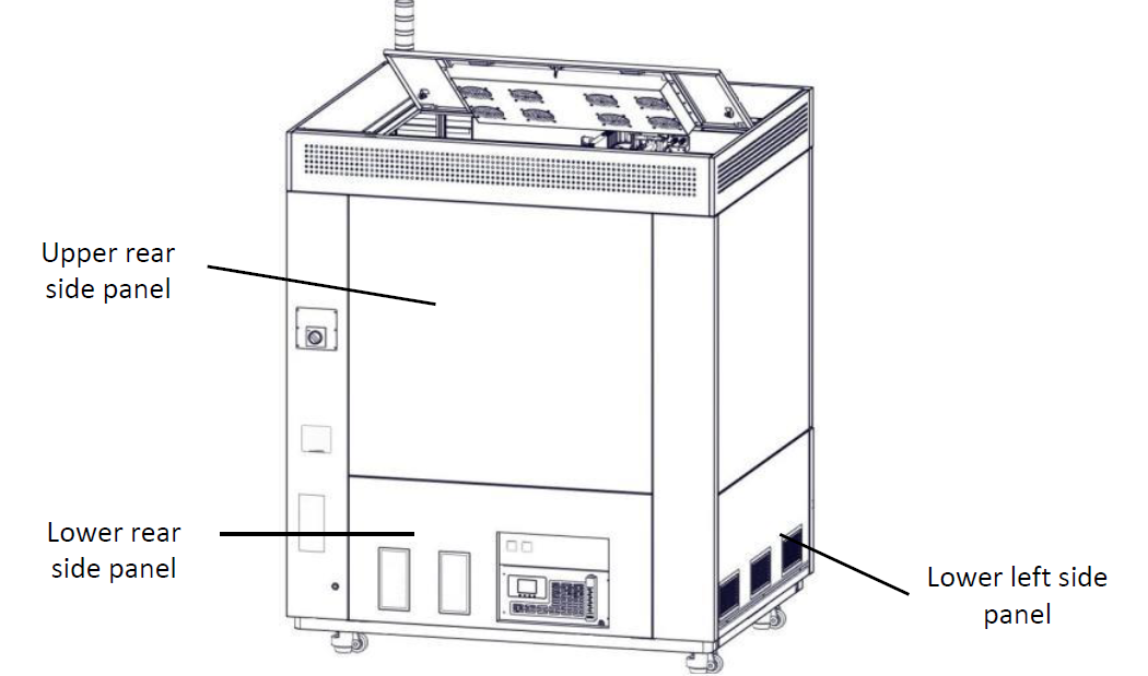
The visible part of the printer's appearance is shown in the figure below.
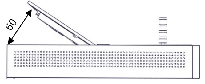
Among them: the front panel of the right electric control cabinet, the left lower side panel and the rear side panel can be disassembled, and the top cover can be opened upward for the maintenance of internal components.
The top cover and front door shall be closed during the printing process and shall be locked by electromagnetic locks.
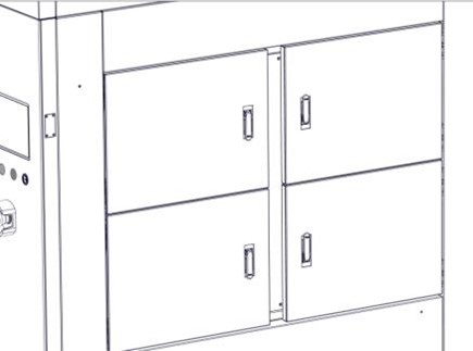
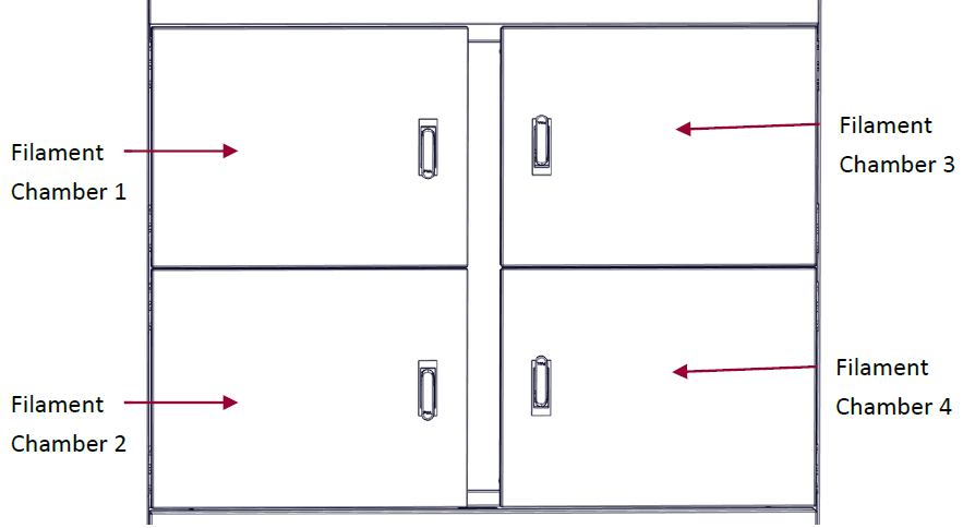
Four separate filament chambers’ doors can be seen on the right, with a rotary wrench that can be opened.
¶ 3.2 Operation interface and door’s switch
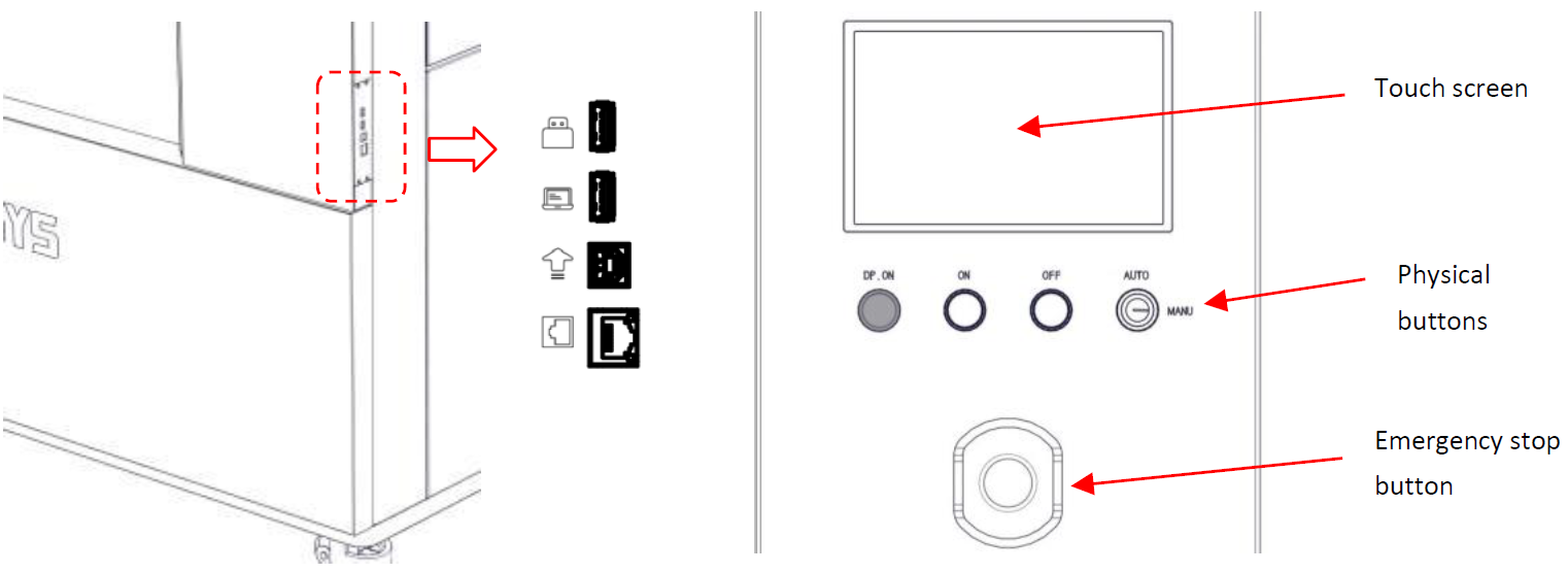
On the right front of the device is the user interaction area, including the touch screen and switch buttons.
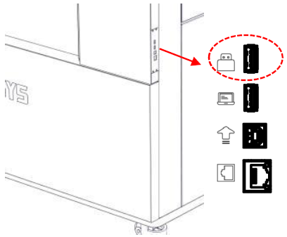
The user realizes the control of printing through the touch screen to get the machine status information. Switch buttons are located at the bottom of the touch screen, including the white "DP.ON/Driver Power ON" button, the green "ON" button, the red "OFF" button, the key-shaped mode selector switch, and the red mushroom-shaped emergency stop button. The USB interfaces and network interfaces are located at the bottom right side of the interaction area.
Turn the mode selector switch to AUTO or MANU by rotating the key. In the AUTO mode, the safety control system is started. After the front door and top cover are closed, press the white "DP.ON" button. In the MANU mode (maintenance mode), some necessary door opening operations can be done. Release the electromagnetic lock through screen operation to open the front door and the top cover.
¶ 3.3 Printing Chamber Assembly
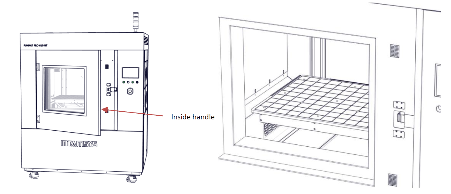
Release the electromagnetic lock through screen operation, the front door can be pulled open from the right side, and then you can see that the printing chamber which contains: front door, buildplate, dual nozzles assembly, copper wire brush, electromagnetic lock, magnetic suction, door sensor, heating and insulation assembly, etc.
When the printing chamber is heated, the bottom plate and the side plate of the stainless steel are at a high temperature. Please do not touch them to avoid scald.
¶ 3.4 Filament Chamber
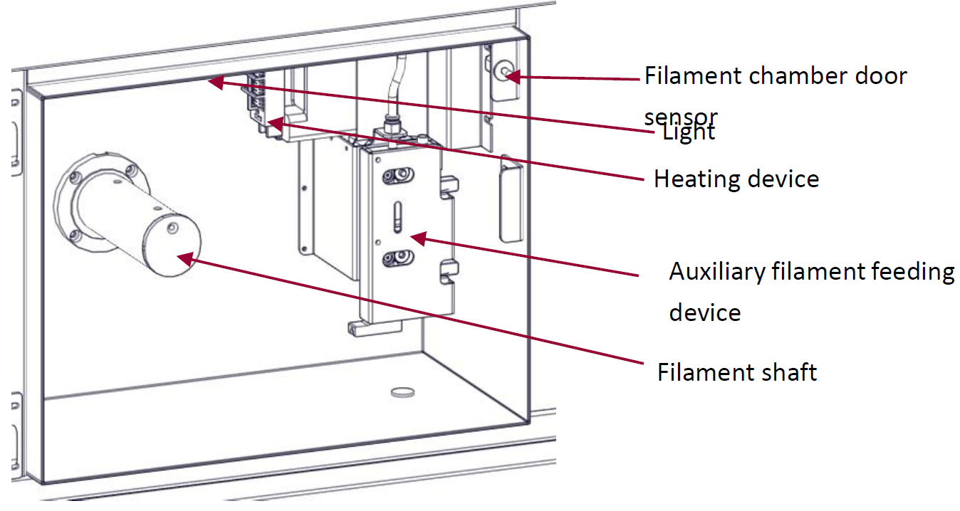
There are altogether four filament chambers, all of which are independent chamber. The filament spool is placed on the filament shaft and feeds filaments to the printing head for sample printing. When the filaments in the filament chamber are used up, the sensor attached on the auxiliary filament feeding wheel automatically detects this and exits the remaining filaments, and then the current filament chamber is switched to the spare chamber on the same side to automatically feed filaments, so as to realize the function of continuous printing after filament replacement. The filament chamber has a heating device, which can be used for auxiliary drying of the filament, with the maximum temperature of chamber up to 50°C. In order to ensure the material to be as dry as possible, the dry compressed air will be injected into the chamber at all times, and the hinge door of the filament chamber should be always kept closed. When material replacement or troubleshooting is needed, the door lock is unscrewed and pulled outward, and the light opens automatically with the opening of the chamber.
¶ 3.5 Printing Head
The printing head part is used to melt the filament and combine it with the motion of the XYZ axis to form the desired model on the printing plate. The whole part has two nozzles, usually the left nozzles are used for printing model materials and the right nozzles for printing support materials. By the overall movement of the right printing head up and down, the switch between the left and right printing head can be realized. Only one printing head can execute printing at the same time.
There are feeding status monitoring sensors (one on each side) on the printing head part, which will alarm upon abnormal feeding. For filament loading and unloading, see Printer Operation section.
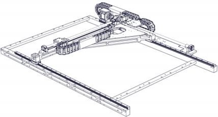
¶ 3.6 X/Y Axis
The X/Y axis part drives the double nozzle extruder to move in the XY plane as instructed.
The X-axis and Y-axis are driven by servomotor to drive the screw. When the machine leaves the factory, the driver has been adjusted to an appropriate state. There is no need to adjust it when it is in use.
¶ 3.7 Z Axis
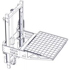
The Z-axis part drives the buildplate to move up and down. It can be repaired by removing the rear side plate.
The trigger piece of the photoelectric sensor is already in the proper position, generally it does not need to be adjusted by the user. Only when the buildplate is manually adjusted may it be necessary for the user to check and adjust the trigger plate position appropriately. Adjust the mounting plate of the photoelectric sensor downward to move the zero position of the buildplate downward and vice versa. The upper end of the two guides has a z-axis mechanical limit block, and the z-upward limit can be adjusted by selecting screws.
¶ 3.8 Caster 16
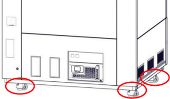
There are 4 casters under the machine, which are used for indoor short distance movement and orientation adjustment. They cannot be used for long distance movement, otherwise they will be damaged.
Casters can be released by clockwise rotation, and can be locked by counterclockwise rotation. After the printer position is determined, the casters should be placed in the locked status, otherwise it will affect the printing quality.
When the printer is transported for a long distance, the printer must be placed on the pallet first and then transported with a forklift. The printer must not be transported directly with a forklift, otherwise the bottom of the printer will be damaged.
¶ 4 User Interface
¶ 4.1 Abstract
This chapter provides an abstract of the main user interface (UI) of FUNMAT PRO 610 HT. Specific printer running information and programs can be found in Section 5 “Printer Operation”. Before using the touch screen, the printer must be powered on.
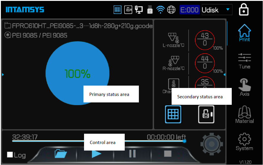
The FUNMAT PRO 610 HT user interface consists of a touch screen located in the middle of the front of the printer. The main screen interface has three main functional areas. These areas are shown in figure below.
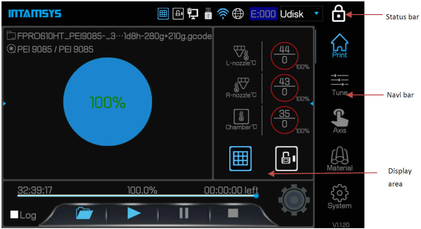
The FUNMAT PRO 610 HT has a hard IPS screen with a 170-degree viewing angle, which gives you a clear view of the screen at all angles, but it's recommended to stand on the front of the screen to make the touch screen easier to use.
Through the screen navigation bar, the following operations can be performed:
• Print operation: Normal print files, preheat and heat preservation settings; progress display, temperature display, etc.
• Tune: The setting of print-related parameters for printing/standby
• Axis: Inching operation on the moving axis of the printer and the extruder
• Material: Material handling, leveling, material management and other operations related to specific materials
• System: The view of System parameters and related System Settings
Click the status bar icon to perform the following actions:
• INTAMSYS Information Query (INTAMSYS icon)
• Open and lock operation (lock door icon)
• Ethernet configuration (Wired network Link icon)
• WIFI configuration (WIFI icon)
• Remote Printing Service configuration (Earth icon)
• Error diagnosis (E:000 icon)
• Print data source selection (drop-down menu)
• Screen lock (lock icon)
¶ 4.1.1 The Status Bar
The status bar is docked at the top of the touchscreen display and appears on every page of the user interface. The status bar displays a variety of information, including the IINTAMSYS logo, system status indicator, network status indicator, error status code, print data source display, and more.
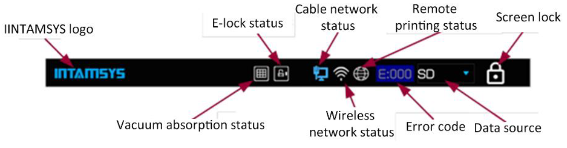
As shown in the figure, the status bar objects above can be clicked for operation.
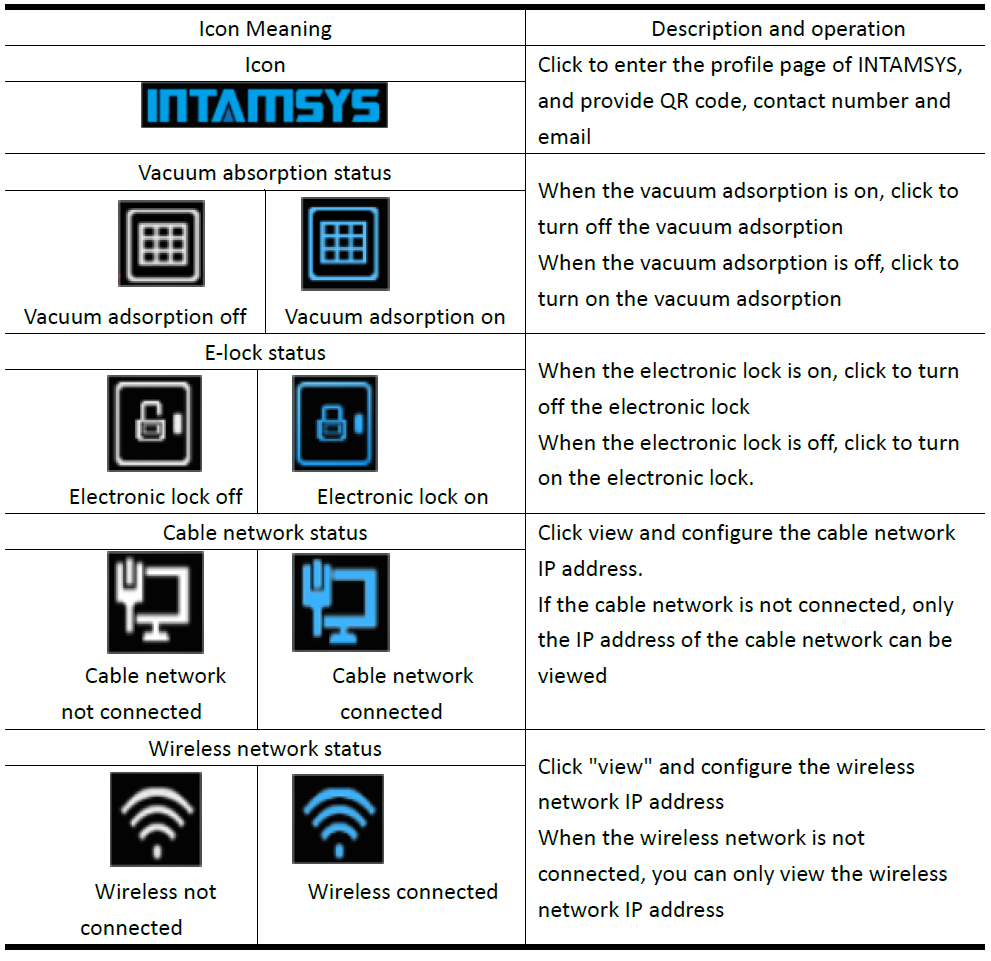
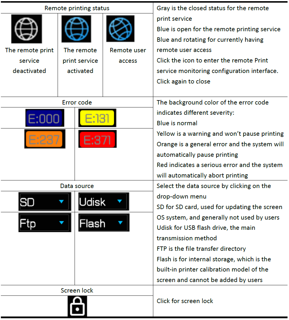
Also: When inserting SD card or USB flash drive, there will be icon prompt in the status bar (only status prompt and cannot be clicked).

When the mouse or keyboard is connected, the status bar will also have an icon prompt (only status prompt and cannot be clicked).

¶ 4.1.2 Navigation Bar
The navigation bar is displayed on each home page of the user interface and provides single-touch access to the printer's Print, Tune, Axis, Material, and System functions. The user interface is broken down into multiple pages that contain related functionality. Selecting a button from the navigation bar will open the page corresponding to that button, allowing you to perform related tasks within that page. If a page contains sub-pages or wizards, additional buttons corresponding to these items are displayed in the display area of the page above the navigation bar.
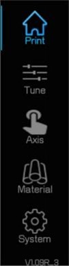
The buttons in the navigation bar are mutually exclusive, meaning that only one button can be selected at any given time. In some cases, all or some of the buttons in the navigation bar are disabled.
¶ 4.1.3 Display Interface
The display interface is used to display the relevant information corresponding to the currently selected functional module, including operation button, text description, picture display or GIF diagram, etc. When the user selects different function modules, the display interface will switch to the corresponding content of the selected function module.
• After power on, the corresponding contents of the print function module will be displayed in this interface by default.
• When you select the corresponding icon in the status bar, the interface will switch to the Settings or display interface related to the status
• After selecting the corresponding function button in the navigation bar, the display interface will switch to the operation interface of the corresponding function module.
• When using the wizard, the display interface will display the contents of the different steps in order of action.
¶ 4.2 Printing Interface
The Print interface consists of three main functional areas that are necessary to select and perform model printing on the machine. These items are highlighted in Figure 4.6. From the Print page, you can select the print file, start, pause, and stop printing, learn how the selected Print file matches the current configuration of the printer, and see the progress of the current print task and estimate the time remaining. To access the print page, press the Print button in the navigation bar.
¶ 4.2.1 The Primary Status Interface
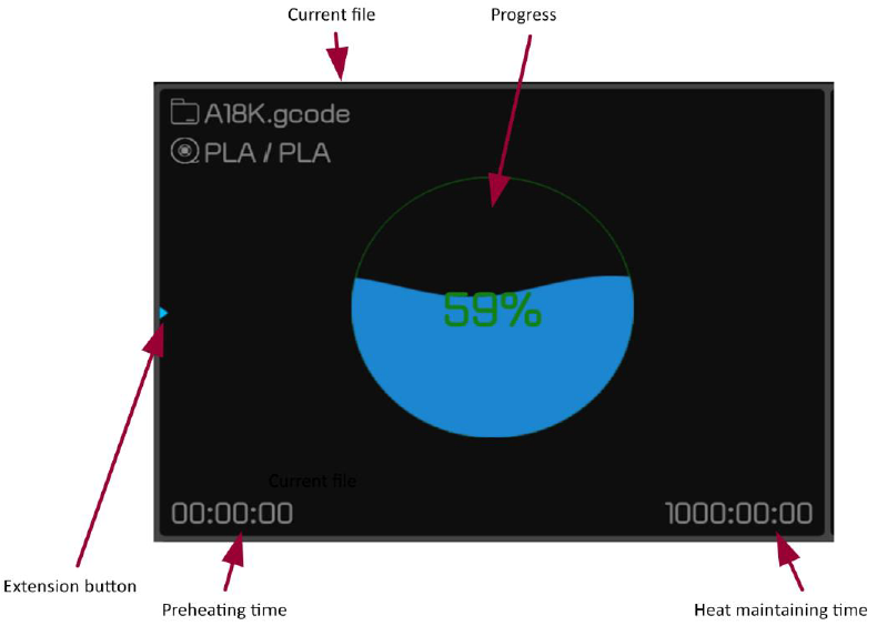
Click the extension button to open/close the setup interface of preheating and heat maintaining in the following figure
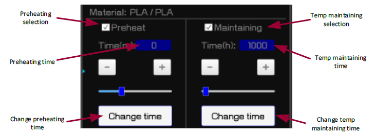
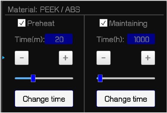
Check the preheat check box to make the heat effective, and the maintain check box to make the heat maintaining effective. The default preheat and heat maintaining time can be adjusted by the slider or "+"/" - "according to the data setting of the material library, and then click" Change Time "to make the time effective. Check the Auto Leveling check box to make each leveling automatic before printing.
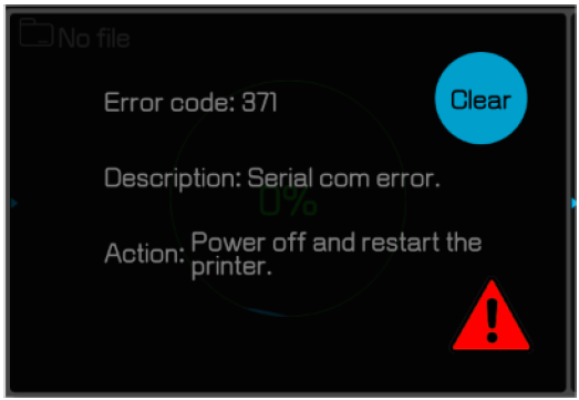
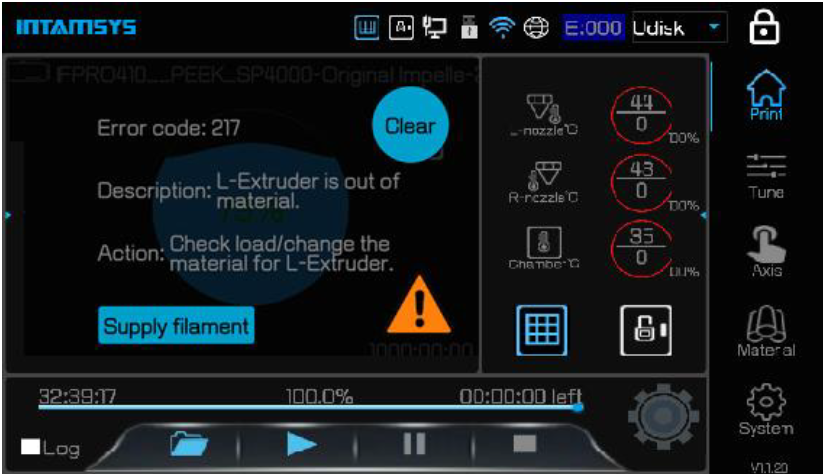
When the system finds the fault, the status bar will display the Error code. If the fault occurs, an Error prompt interface will pop up, as shown in Figure below, which contains the Error code, Error Description and Suggested Actions. After troubleshooting, click the "Clear" button to clear the error.
¶ 4.2.2 The Secondary Status Interface
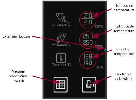
The secondary status interface displays the current temperature status of different components. The temperature display module is shown above the horizontal line as the current temperature, below the horizontal line as the target temperature, and the percentage at the lower right corner as the progress. Clicking the Extension button displays the status of the extension parameters.
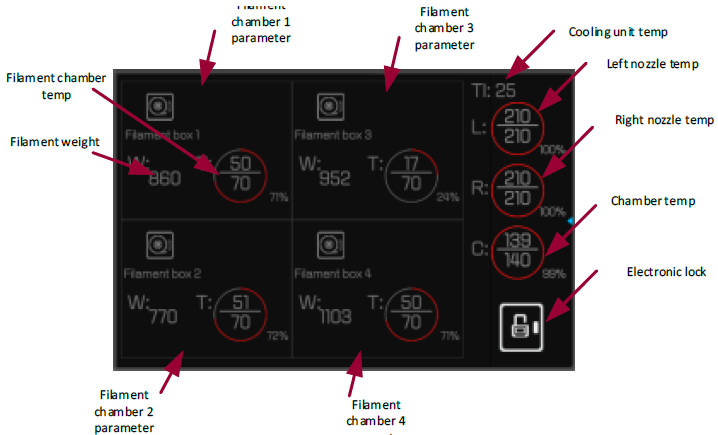
Click Wl or Wr to perform material weight calibration operation.
¶ 4.2.3 The Control Interface
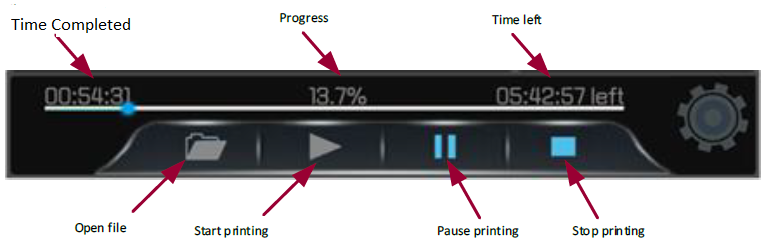
The control interface is used to display printing progress and control printing, including open, start, pause, stop and other operations. The gear rotates when the print starts, and stops or pauses when the gear stops.
¶ 4.2.4 Developer Mode
In the system settings screen, click "Developer mode" to enable it (enabling is not recommended during normal use).

The control interface will expand into the following shape:
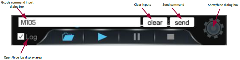
Click on the status gear to show/hide the command input box.
Check the Log check box to show that the Log display area is open.
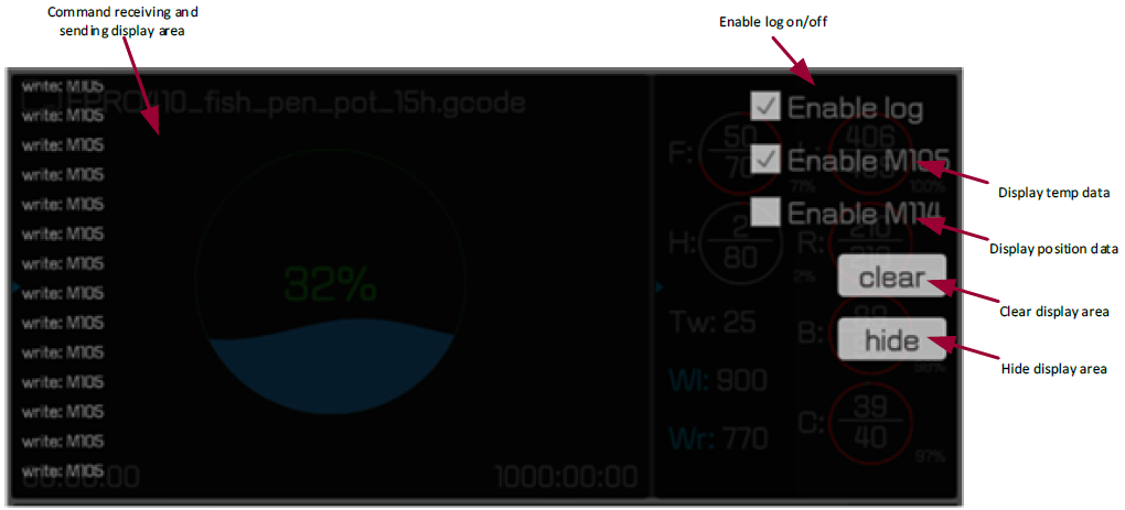
The Log display can be used to assist in troubleshooting.
Note: Please cancel Enable log during printing, otherwise it may affect the printing speed and quality.
¶ 4.3 Tune Interface
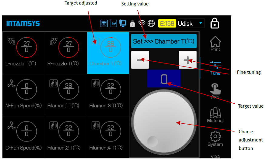
The tune interface is used to adjust print-related parameters, including left Nozzle temperature (LNozzle T), the right Nozzle temperature (R-Nozzle T), Chamber temperature (Chamber T), Filament Chamber temperature (Filament Chamber T), the printing Speed (Print Speed), Material flow (Material flow), left Fan Speed (L-Fan Speed), the right Fan Speed (R-Fan Speed), click on the corresponding square to choose in scratchable latex, adjust the target, click set button to complete the set.
¶ 4.4 Axis Interface
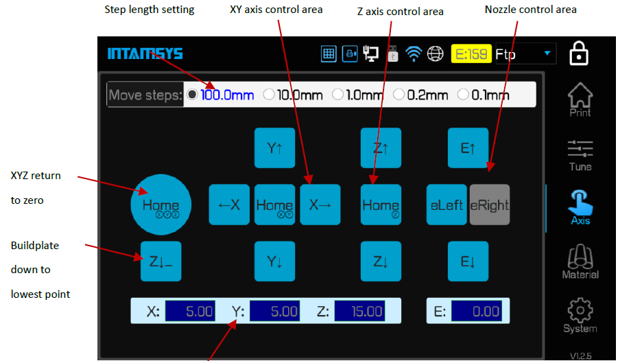
The axis interface is used for manual operation of buildplate, print heads and extrusion and materials withdrawal.
¶ 4.5 Material Interface
Material interface is for material setting, loading/unloading, automatic/manual leveling and calibration, and material database management.
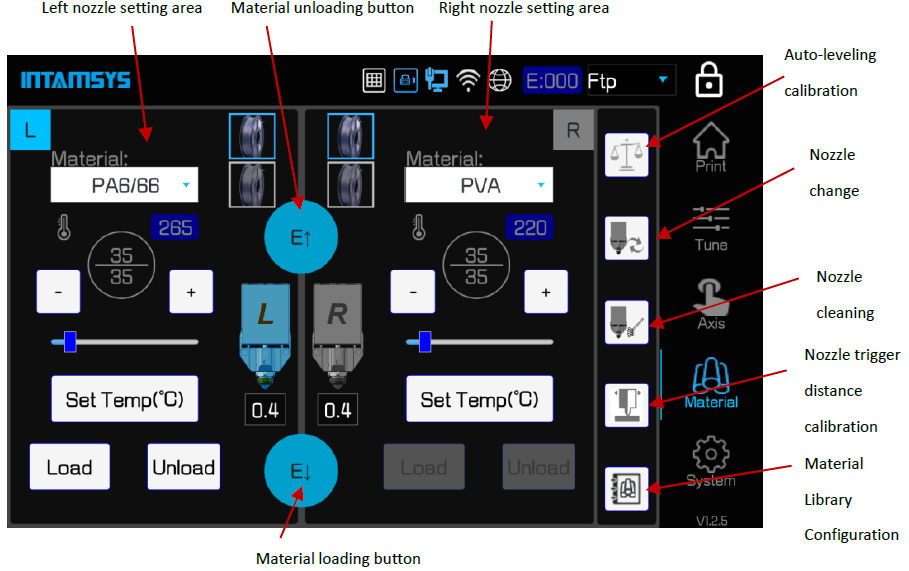
¶ 4.5.1 Nozzle Setting Interface
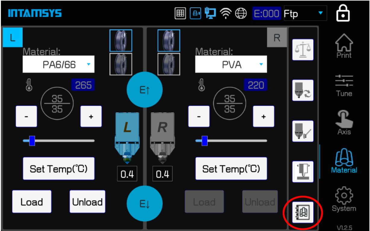
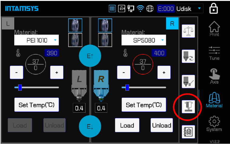
Figure below is the nozzle setting interface. Click the nozzle icon to switch the current nozzle. The nozzle setting interface can be used for material selection, nozzle temperature setting, material loading/unloading (see Section 5.2 of Chapter V) and other operations. Click the "Automatic leveling and Calibration button" to enter the automatic leveling and calibration interface (see Chapter 5). Click the " Nozzle change" button to enter the nozzle replacement interface (see Chapter 5). Click the "Library Management button" to enter the material library configuration interface.
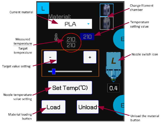
¶ 4.5.2 Material Library Configuration Interface
The material library configuration interface is used for browsing the system material library and customizing the user material library.
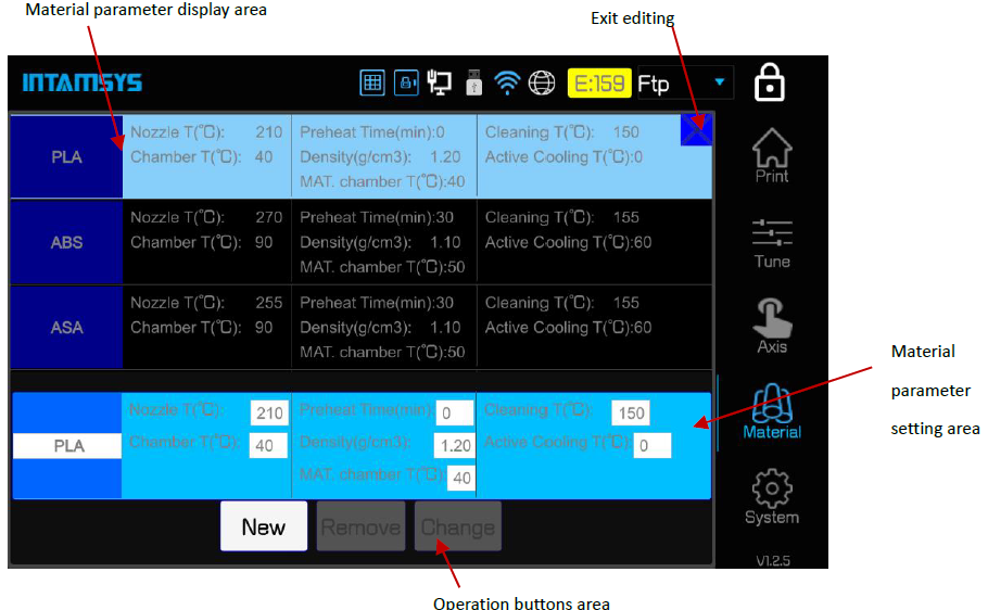
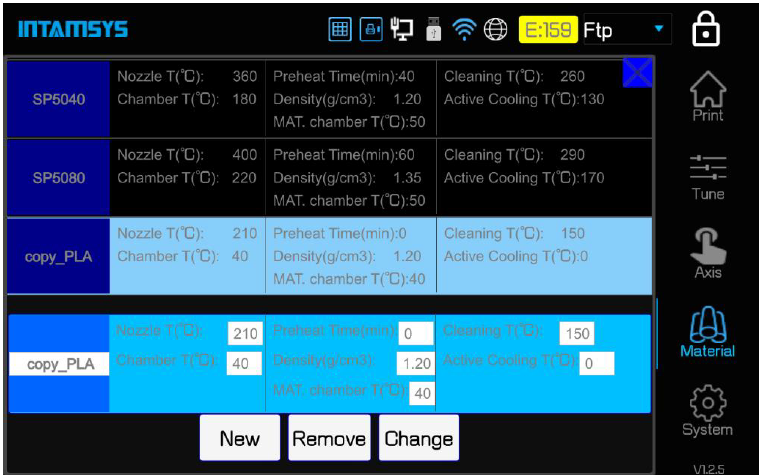
The material operation interface is used to edit materials. The material parameters display interface shows all materials. Other materials can be displayed by sliding up and down. The built-in parameters of the printer cannot be edited, changed, or deleted. However, the user can select the corresponding material parameter column and click "New" to copy the current parameter, and add a material item at the bottom. At this time, the material parameter can be changed and automatically saved. For material parameters added by the user, the user can click "Remove" to remove them or click "Change" to update them.
¶ 4.6 System Interface
The system interface is used for system-related Settings, including system information viewing and upgrading, system-related parameter setting, printer system parameter setting, etc.
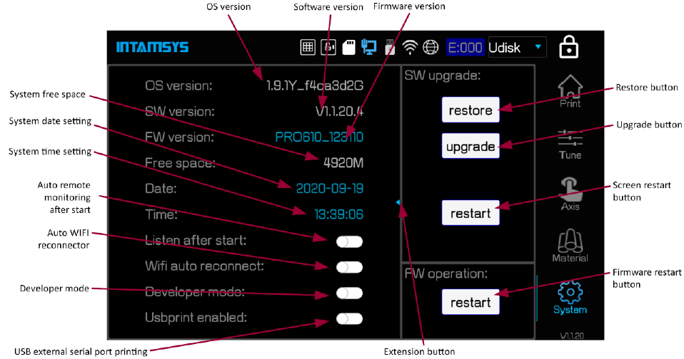
Software Upgrade Operation Interface (SW Upgrade):
- Restore: The Restore button can be used to restore the last version of the screen software
- Upgrade: A button to upgrade the screen program version and update the material library attributes. After inserting the USB flash drive with the new version of the software, click "upgrade"
- Restart: Restart the screen after the upgrade
Firmware Upgrade Operation Area (FW operation):
- Restart: Used to restart the firmware, that is, restart the motion control card
System setting area:
- Listen After Start: It is set to allow remote access automatically after the system restarts, or you can manually click the "Listen" button in the remote Printing service area to start manually.
- Developer mode: Enables Developer mode to send custom G code and open Log for troubleshooting.
- USB print enabled (USB Print mode) : This mode enables remote serial port direct printing through the USB serial port on the smart panel. In the case of enabling, the motherboard will interrupt communication with the screen and switch to USB serial device communication. Used for printing with USB serial port. Note: This system setting will not be saved and will revert to the closed state after restart.
Click the extension button to enter the system Settings extension interface.
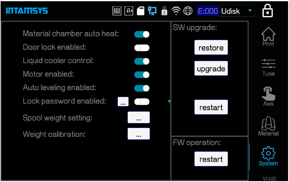
Material chamber auto heat: Material chamber automatic heating switch, blue for effective (enabled), grey as invalid (canceled).
- Door lock enabled: electronic lock switch, blue for effective (lock), gray as invalid (open)
- Liquid cooler control: Control switch of liquid cooling unit, blue for liquid cooling unite activated, gray for liquid cooling unit deactivated
- Motor enabled: Motor switch, blue for on, gray for off
- Auto leveling enabled: Automatic leveling switch, blue for on, gray for off
- Lock password enabled: Lock screen password switch, blue for on, gray for cancel. Click ‘’…'' to enter the password change area. The default password is "intamsys"
¶ 4.7 Other Interfaces
¶ 4.7.1 Remote Printing Interface
The remote printing interface is used to start the remote printing service, which can be entered by clicking the remote printing status icon in the status bar.

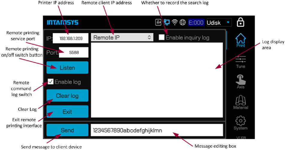
Note: Before using the remote printing service, the IP address needs to be configured successfully. Only one of wired or wireless network configuration IP can be selected. Currently, IP configuration of both networks is not supported at the same time.
¶ 4.7.2 Wired Network IP Setting Interface

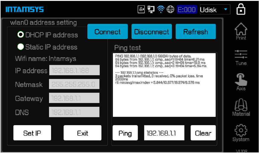
Click the wired network status icon in the status bar to enter the wired network IP setting interface as shown in figure below. Select DHCP IP address (dynamic IP address) or Static IP address (Static IP address) in the setup area. For static IP addresses, fill in IP address, Netmask, Gateway and DNS (domain name server) according to the actual situation. The test area can Ping packets to test whether the network connection is successful.
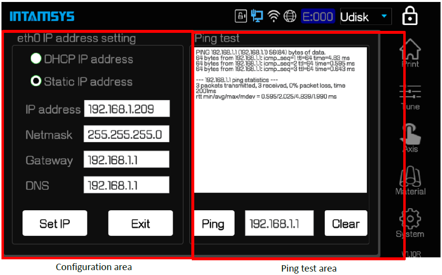
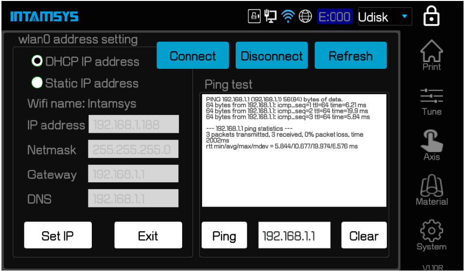
After the IP address is configured, you can click the "Ping" button to test the connection between the printer and the gateway. Figure below shows the interface for testing the successful connection.
¶ 4.7.3 Wireless Network IP Setting Interface
The wireless Network (WIFI) IP setting interface is shown in figure below. Click the WIFI icon in the status bar to enter.
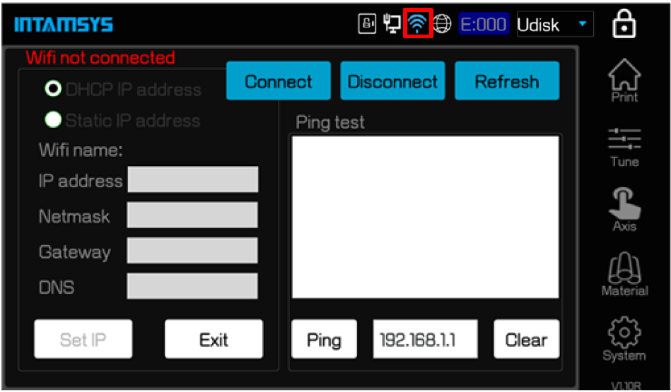
After entering the wireless network setting interface, click "Connect" button to enter the hotspot connection interface as shown in figure below and select WIFI hotspot.
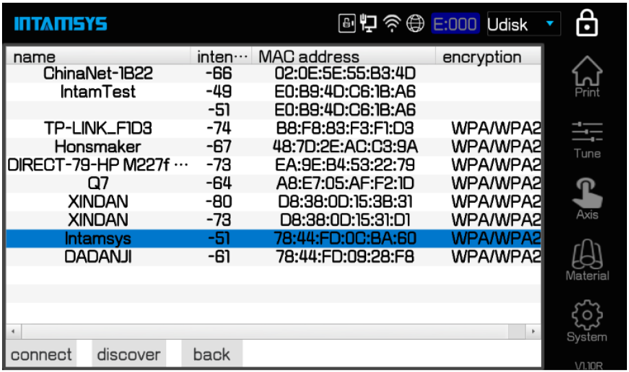
Click the "Discover" button to find the WIFI hotspots that can be connected, select the hotspots that you want to connect, and then click the "Connect" button to prompt for password. After the password is entered correctly, the WIFI status icon in the status bar will turn blue, as shown in figure below, indicating successful wireless network connection.
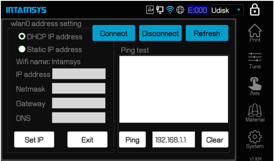
In Ffigure belwo, select DHCP IP Address and click the "Set IP" button to get dynamic IP. Or select Static IP Address, Static IP mode, and then manually enter the IP address to be a Static IP.
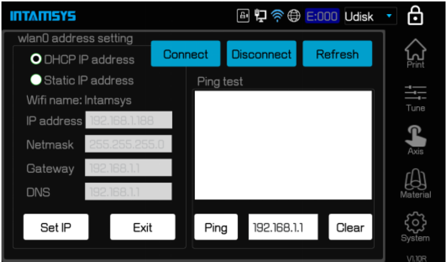
After successful configuration, you can also click the "Ping" button and select the destination IP address to Ping to verify whether the connection is successful.
Note: The default PING gateway address, if there is no gateway in the LAN, needs to change to other valid address test.
¶ 5 Printer Operation
The chapter describes the basic steps for operating FUNMAT PRO 610 HT.
¶ 5.1 Basic user operation
¶ 5.1.1 Power on the Printer
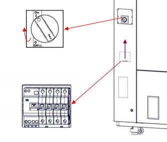
1. First, confirm whether the air switch at the lower right of the equipment is closed. If not, push up the rotating operating handle to complete closing. When the air switch is closed, turn the upper rotary switch to ON to supply power to the equipment.
2. When the printer is powered on, the power off button on the front of the printer and below the screen lights up a red indicator indicating that power is supplied.
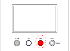
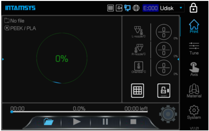
3. Press the green power button at the bottom of the printer screen and it lights up with a green indicator. At the same time, operate the screen to enter the startup interface, and the printer starts. After around 30s waiting, the screen will display the following interface, indicating the completion of boot.
¶ 5.1.2 Turn off the Printer Power
Press the red shutdown button located at the bottom of the printer screen, and the screen prompts "Confirm shutdown". If you confirm shutdown and click the screen confirmation button, you will enter the shutdown process. If the chamber temperature is higher than 50℃℃, press the red shutdown button, and the screen prompts "The equipment will shut down when the temperature drops below 50℃℃".
Note that this action simply shuts down the printer. To completely disconnect the printer's power, pull down the rotating handle of the main power switch to complete the power off.
If the printer is not in use for a long time, turn the knob to OFF, and disconnect the AC power supply from the power line.
¶ 5.2 Materials, Filament Chamber and Printing Head
Note: When loading and unloading materials, make sure there are no prints or other residue on the printing buildplate. Because, when this operation is performed, XYZ will perform a zero operation. Prints or other residue on the printing buildplate will collide with the printing head or XY motion frame.
The material chambers of the printer are equipped with 4 chambers, which can be installed with 2 rolls of each material of the printing head. The upper and lower positions on the left are supplied to the left nozzle for printing, mainly for printing model materials, while the upper and lower positions on the right are supplied to the right nozzle for printing, mainly for printing supporting materials. In order to perform dual nozzle printing of the parts, please ensure that there is at least one roll of material installed in each filament chamber on the left and right sides.
¶ 5.2.1 Load the Material
The information in this section will guide you through the process of loading the material into the nozzle. When completing the required steps, be sure to refer to the instructions displayed on the touch screen.
1. Material chambers are located on the right side of the printer, divided into 4 independent chambers;
2. Turn the door handle to open the material chamber;
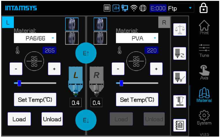
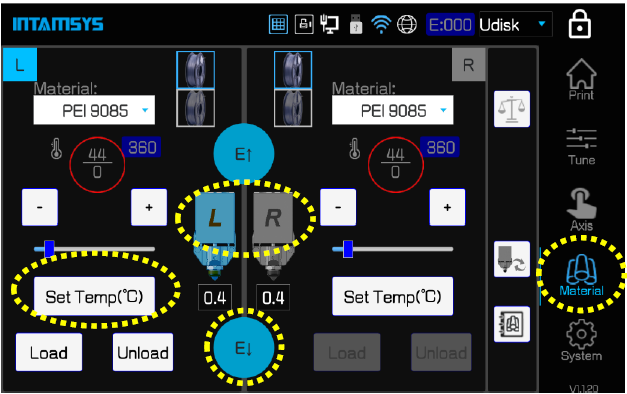
3. In the screen operation interface, select the "Material" button, and the interface similar to the figure below will be displayed. Click L (left nozzle) /R(right nozzle) to select the nozzle to be loaded with materials. When the filaments pass through the drive wheel in the filament chamber and the auxiliary filament feeding wheel, it means that the filaments are successfully loaded in the filament chamber. The icon highlighted in blue represents the activated nozzle. The printer is equipped with two filament chambers for both the left and right nozzles. After selecting the nozzle to load materials, select the filament chamber for the corresponding nozzle to load materials.
4. Select the type of Material to be loaded from the Material drop-down menu. (If the loaded material is not included in the option, please refer to the New Material option to add the material category.)
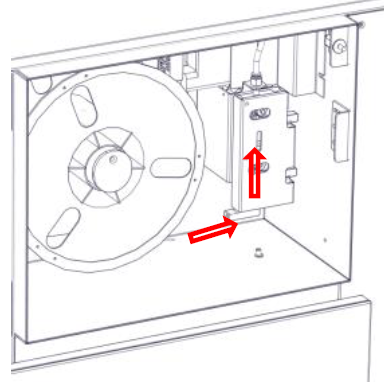
5. Insert the material spool into the material shaft. The material coil should be in the upper outgoing line direction, that is, the tangential direction of outgoing line should be located in the lower part of the material shaft (see below figure), so as to ensure more smooth material loading.
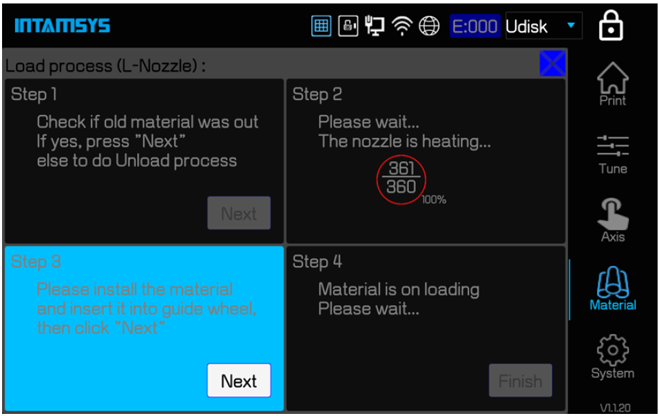
6. Click the Load button on the screen to load the material in 4 steps. Load the material according to the on-screen instructions for each step.
Step1: Check if old material was out. If yes, press ‘Next’, else to do Unload process;
Check whether there is material residue in the chamber or guide tube. If there is no material, click "Next" directly to perform the Next operation. If there is any material, click "×" in the top right corner of the dialog box to close the dialog and perform the "Unload" operation to Unload the original material. See 5.2.2 for unloading materials.
Step2: Please wait…The nozzle is heating…
This step is mainly to heat the nozzle and wait for the nozzle to be heated to the melting temperature of the material before proceeding to the next step. The target temperature and heating time varies from material to material, please wait patiently.
Step3: Please install the material. And insert it into extruder.
Insert the ends of the material between the auxiliary wire feeding gears and place them in place. Click "Next" again, the auxiliary material feeding gear will accelerate the material loading.
Step4: Material is on loading. Please wait…
The gear will transport the material quickly first, and then slowly when it is close to the nozzle. The whole conveying process is divided into "fast-slow". Filament feeding has two stages:
Stage 1: It counts as a percentage before the filament is delivered to the printing head encoder, and the progress in the first stage is 70% to 80% depending on the specific length of the feeding pipes of the upper and lower filament chambers.
Stage 2: It counts as time after the filament is delivered to the encoder. Filament feeding is slow in this section, and it takes a total of 35 s, with visible filament extruded from the printing head.
7. If the screen shows "Load Failed", close the dialog box first, then click "Set Temp" to keep the temperature, then long press "E↓" until the filament are ejected from the nozzle; Or close the dialog box, and then click the "Load" button again to repeat the operation and try to Load the material again.
Note: In any step of loading material (such as Step3 or Step4 which is not finished yet), if it is found that the material has been extruded already from the nozzle, click "Finish" button in the dialog box “Step4” to finish and complete the loading.
¶ 5.2.2 Unload the Material
The information in this section will guide you through the process of unloading the material from the nozzle and the guide tube. When completing the required steps, be sure to refer to the instructions displayed on the touch screen.
1. In the screen operation interface, select the "Material" button, and the interface similar to "loaded Material" will be displayed. Click L (left nozzle) /R (right nozzle) to select the nozzle to unload the material. The icon highlighted in blue represents the activated nozzle.
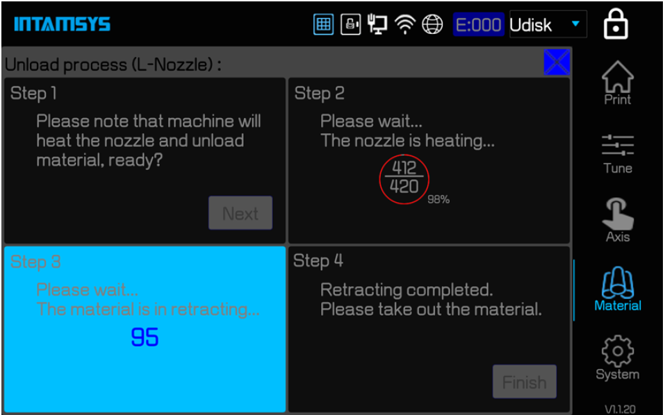
2. Click the Unload button on the screen to Unload materials in 4 steps. Unload the material according to the prompts on the screen at each step.
Step1: Please note that machine will heat the nozzle and unload material, ready?
The printer is about to unload the material. Click "Next" to start this operation.
Step2: Please wait…The nozzle is heating…
First, the printer will heat the nozzle of the unloaded material. It needs to wait until the nozzle is heated to the temperature of the unloaded material before proceeding to the next step.
Step3: Please wait…The material is retracting…
When the material unloading temperature is reached, the material begins to be fed slowly, and then exit slowly, and finally exit rapidly below the drive wheel of the filament chamber.
Step4: Retracting completed. Please take out the material.
The material unloading process will be completed in 2min.
3. Open the material chamber, take out the filament roll, and rewind the 2 m exiting filament onto the filament spool. To prevent entanglement the next time you use the unloaded material, be sure to insert one end of the filament into a hole in the side of the coil.
4. Close the chamber door to prevent moisture from entering.
¶ 5.2.3 Edit the Material
Click the "Material" button, and then select the edit Material library button in the lower right corner to enter the edit Material library interface. The following process parameters of the material can be edited:
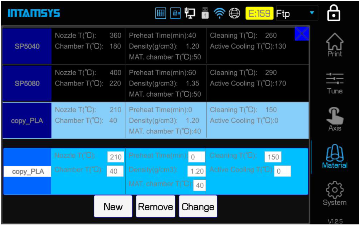
The material operation interface is used to edit materials. The material parameters display interface shows all materials. Other materials can be displayed by sliding up and down. The built-in parameters of the printer cannot be edited, changed, or deleted. However, the user can select the corresponding material parameter column and click "New" to copy the current parameter, and add a material item at the bottom. At this time, the material parameter can be changed and automatically saved. For material parameters added by the user, the user can click "Remove" to remove them or click "Change" to update them.
Note: The material process parameters here are only used for the operation of the printer itself other than formal printing, including loading material, unloading material, XY offset calibration, preheating, heat maintaining, cleaning nozzle, changing nozzle, chamber active cooling, etc. When printing, the printer will execute the loaded G-Code instruction file instead of the preset parameters in the printer.
¶ 5.3 Change Nozzles and Clean Nozzles
¶ 5.3.1 Change Nozzles
The printer is equipped with two nozzles (left nozzle and right nozzle)
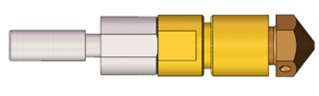
Before replacing the nozzles, it is required to heat the printing head and unload the material from the nozzles (perform two strokes of E100 for material unloading)
The steps to change the nozzle are as follows:
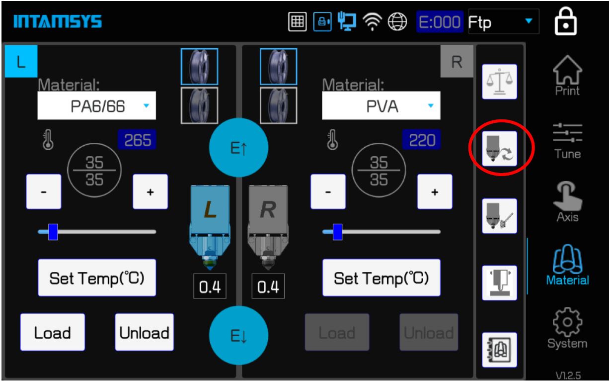
1. Click the "Material" button to enter the Material interface.
2. Click the "Change nozzle" button in the lower right corner of the screen. The printing buildplate will move to the lowest position, and the printing head will move to the middle position of the chamber. Follow the on-screen instructions step by step.
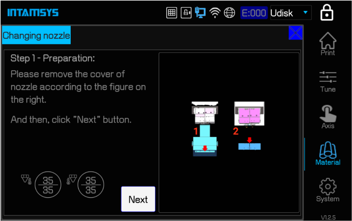
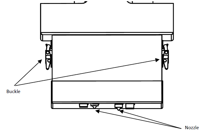
3. Manually remove the printing head cover. Hold the cover with one hand, remove the buckle with the other hand and pull out the clasp hook. The buckle is located on both the left and right sides of the cover.
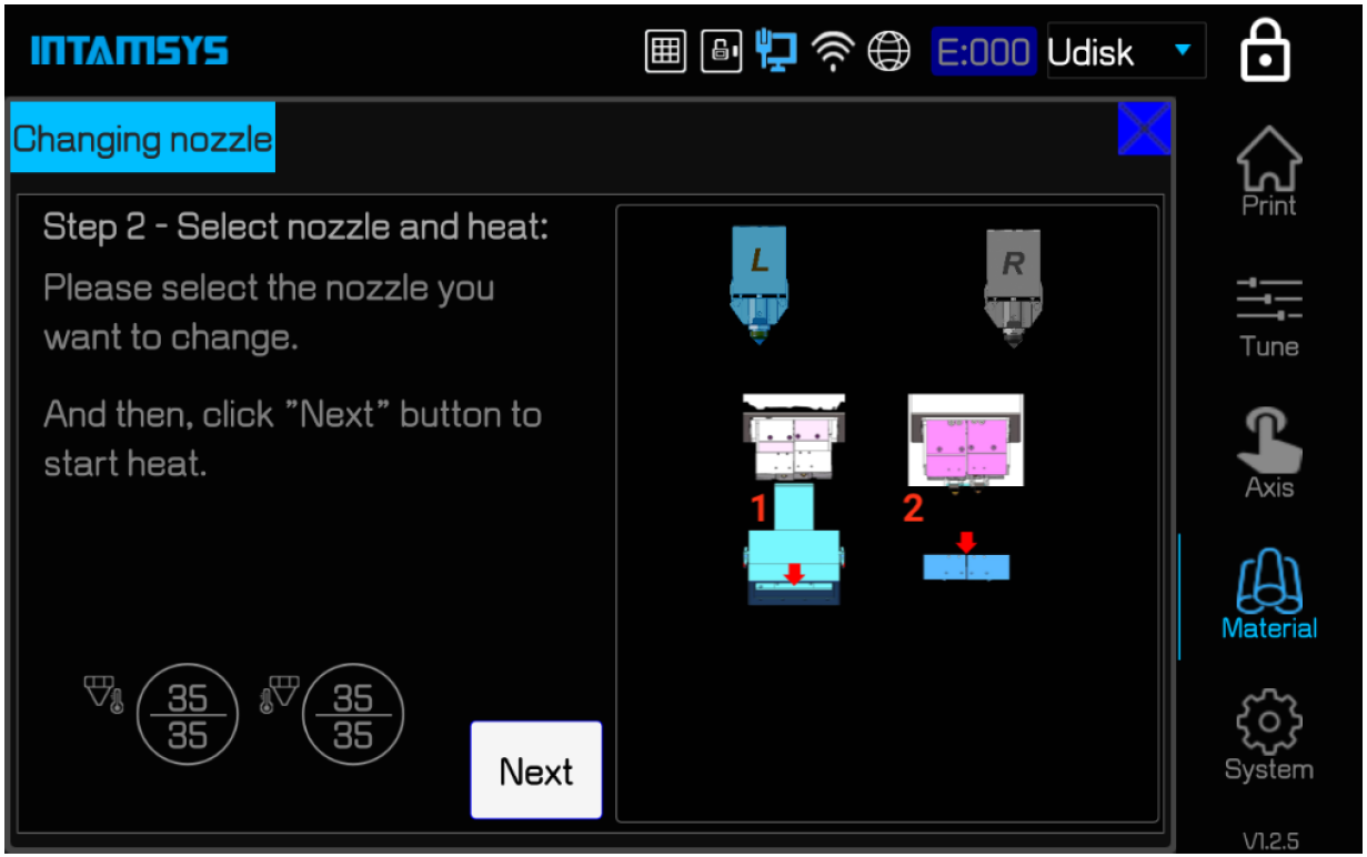
4. Select the nozzle L/R that needs to be replaced. After clicking the "Next" button, the nozzle will be automatically heated to the melting temperature of the material.
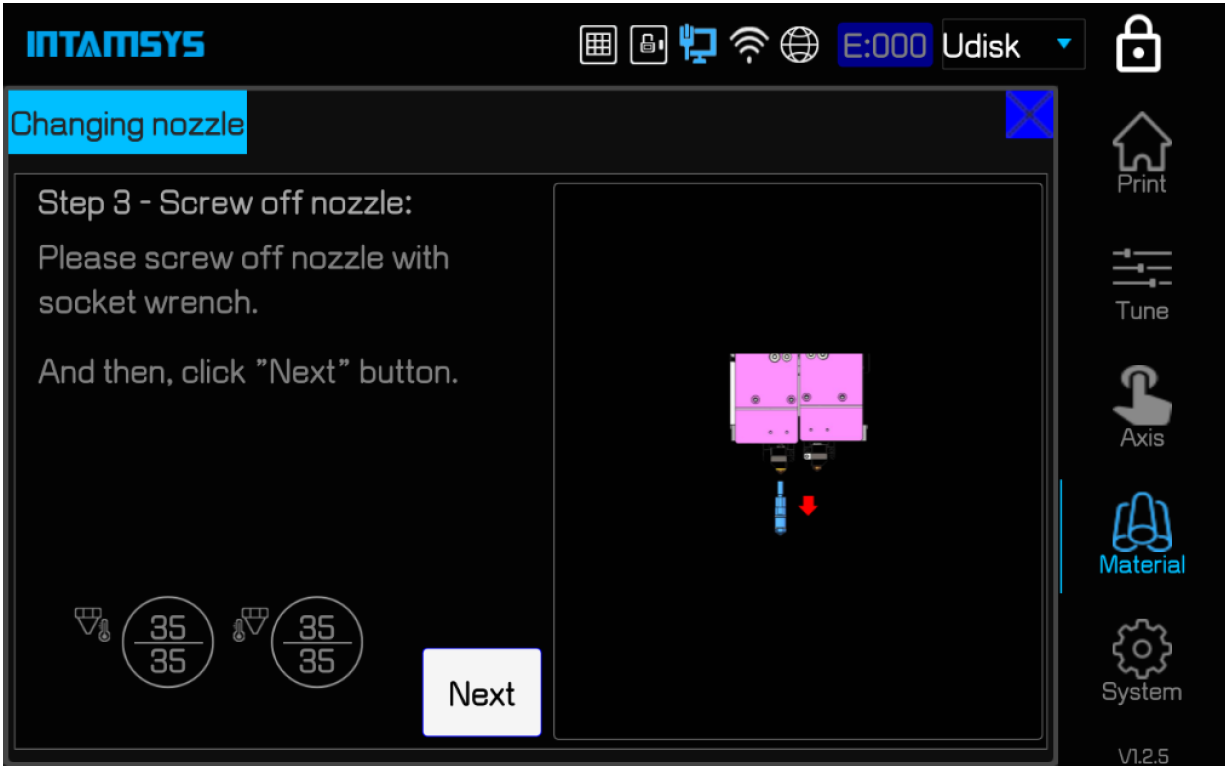
5. After the nozzle reaches the target temperature, loosen the screws on the front and side of the fan cover with 2.5 mm inner hexagon wrench and remove the fan cover. Then loosen the 2 fixing screws on the heating block and take out the nozzle.
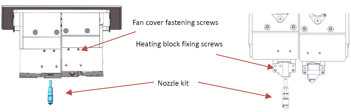
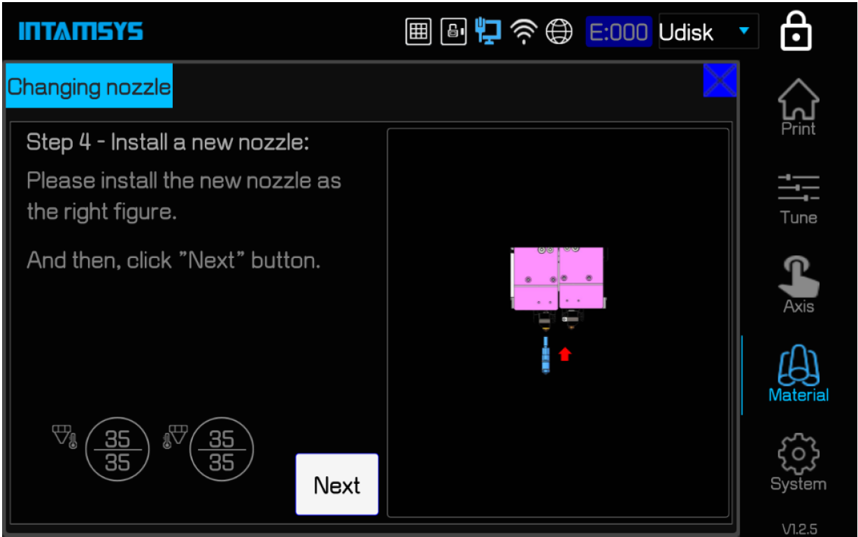
6. Change the new nozzle and tighten the screws with wrench.
7. Click the 'Next' button to complete the nozzle installation, or click the 'Change Another' button to Change the nozzle of the other printing head as indicated.
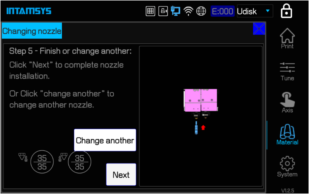
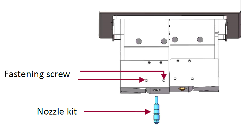
8. Install the printing head cover and set the diameters of the left and right nozzle respectively on the screen. Finally, click the Finish button to Finish.
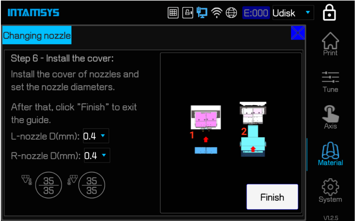
Note: After changing the nozzle, Z offset calibration, printing head height difference calibration, automatic adjustment and XY offset calibration must be implemented in turn to ensure normal printing.
¶ 5.3.2 Clean Nozzles
The cleanliness of the nozzle directly affects the accuracy of calibration and automatic leveling, and also affects the quality of printing. Therefore, it is necessary to clean the surface of the nozzle before each calibration, auto-leveling and printing.
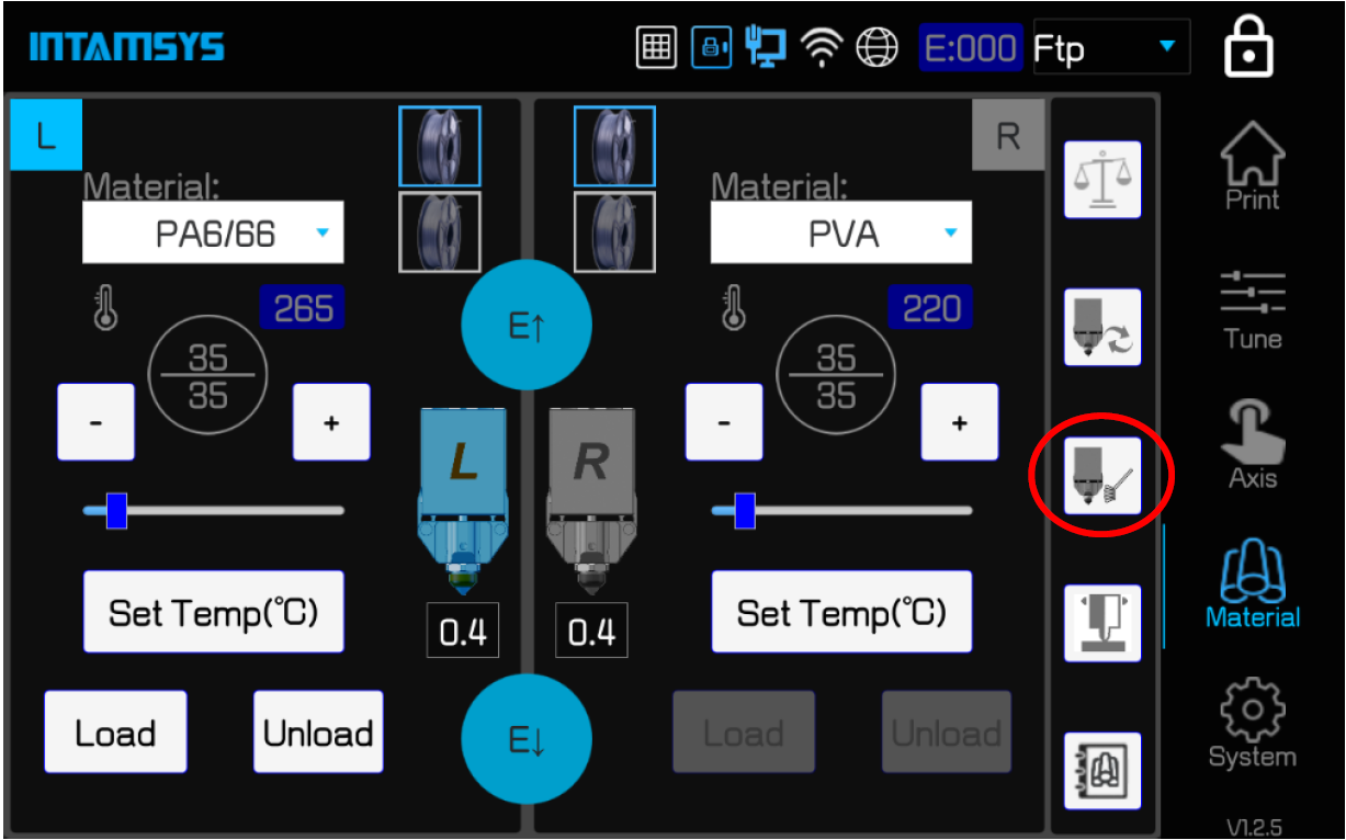
The steps to clean the nozzle are as follows:
1. Click the "Material" button to enter the Material interface.
2. Click the "Clean and Change nozzle" button on the right side of the screen. The buildplate is moved to the low position and the printing head is moved to the middle position of the chamber for convenient operation.
3. The tools needed to clean the nozzle include copper brush and tweezers. Follow the instructions on the screen. The nozzle cleaning is divided into three stages: (1) the nozzle will be automatically heated to the extrusion temperature of the material at first; (2) Then reduce to the unloading temperature of the material, at which point the material is just in the state of softening; (3) Reduce to room temperature. Each stage requires the nozzle to be cleaned.
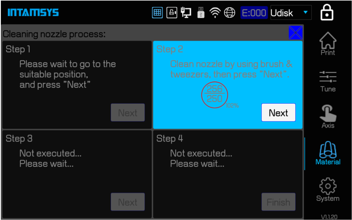
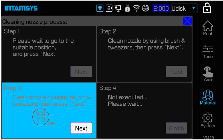
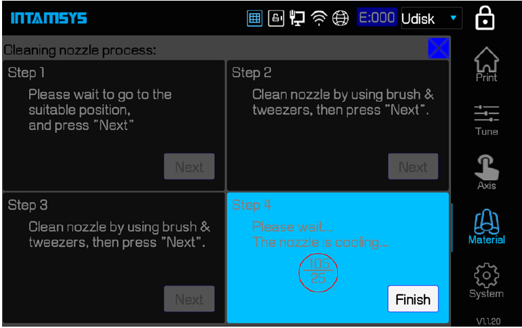
Note: For the leveling and calibration steps, the cleanliness of the nozzle is required to be extremely high. After cleaning the nozzle, there must be no residual material at the tip of the nozzle.
¶ 5.4 Change the Material
¶ 5.4.1 Change the Material before Printing
If the type of Material needs to be changed before printing, in addition to changing the Material at the "Material" interface, the print nozzles needs to be changed accordingly. Different nozzles should be used for printing different materials. If you want to share one nozzle for different materials, the temperature of the printing nozzles must be very close to each other. It is recommended that the temperature difference should not exceed 50℃℃.
Note: Do not print too low melting point material with a nozzle that prints too high melting point material. For example, printing ABS with a nozzle that prints PEEK will cause nozzle block and printing failure.
If the material types before and after are the same or the temperature of the material printing nozzle is similar, there is no need to change the nozzle. The steps are as follows:
1. Unload old materials. Refer to 5.2.2 for detailed steps;
2. Select the new material to be loaded and perform the loading operation. Refer to 5.2.1 for detailed steps;
If the material types before and after are inconsistent or the temperature of the material printing nozzles is greatly different, steps to change the nozzles shall be added, and correspondingly, Z offset calibration, leveling and XY offset calibration shall be performed. The steps are as follows:
1. Unload old materials. Refer to 5.2.2 for detailed steps;
2. Change nozzles. Detailed steps refer to 5.3.1;
3. Select the new material to be loaded and perform the loading operation. Refer to 5.2.1 for detailed steps;
4. Follow the steps of Z offset calibration, leveling and XY offset calibration steps.
¶ 5.4.2 Change the Material during Printing Process
The printer is equipped with automatic material changing function during the printing process. For example, before printing, the upper and lower filament chambers corresponding to the left nozzle are filled with materials. When the upper filament chamber of the left nozzle is used up, the system will automatically switch to the lower filament chamber and use that to continue printing.
If requiring continuous printing of multiple filament rolls, it is necessary to manually change the materials in the empty filament during the printing process. The steps are as follows:
1. Pull out the end of the withdrawn material;
2. Then insert the end of the new material between the auxiliary feeding gear.
When switching again, the new material in the filament chamber can continue to print.
¶ 5.4.3 Pause Printing Process then Change the Material
If the printer needs to change the printing material while it is printing, the steps are as follows:
1. Click the "pause" button in the interface of "Print" and wait for the Print head of the printer to stop printing and move to the default position for material changing;
2. Unload old materials. Refer to 5.2.2 for detailed steps;
3. Install and load new materials. Refer to 5.2.1 for detailed steps;
4. The material loading is finished, click the "Start" button in the interface of "Print" to continue printing.
¶ 5.4.4 Replenish Material after Missing Material Alarm
When the materials in the two filament chamber of one of the nozzles are used up, the printer will pause and the screen will pop up an alarm code to prompt the user to change the materials. Click the “Supply filament” button on your screen and use the following option to replace the material as indicated on the screen:
1. First, minimize the alarm window and identify the filament chamber that needs to be replenished on the Material Interface.
2. Load new material.
3. After loading, click the start button in the interface of "Print" on the screen to continue printing.
¶ 5.5 Basic Operation for Executing Printing
¶ 5.5.1 Equipment Preparation
To prepare equipment for printing:
1. Turn on the power of the printer (see 5.1.1 for details);
2. Remove any print debris that may remain on the side nozzle brush in the chamber and in the dump box;
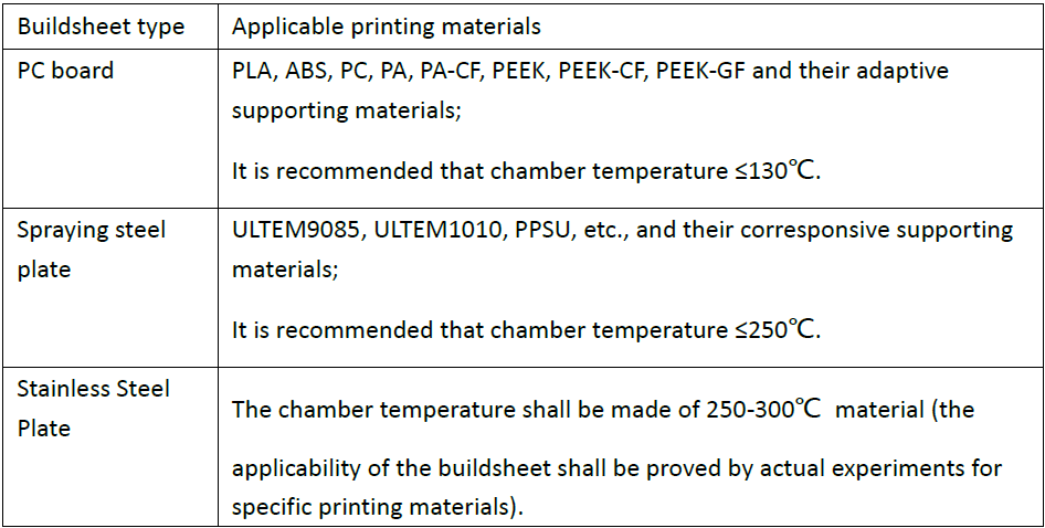
3. Clean the vacuum adsorption buildplate and install the special printing buildsheet. The printer adopts vacuum adsorption to fix the printing buildsheet. In order to ensure the reliability of adsorption, debris, dust particles and other foreign matters must be removed from the surface of vacuum adsorption buildplate before installing the buildsheet. According to the requirements of the printing material, different buildsheet will be selected accordingly. What we suggest suitably for printing buildsheet material is polycarbonate board (PC board), spraying steel plate and stainless steel plate. When using PC board and spraying steel plate for printing, it can be printed directly without any gluing on the surface. Please select the correct type of buildsheet according to the type of printing materials. The print buildsheet can be reused without any damage. In particular, the reused print buildsheet should be cleaned of the remaining print materials.
4. Load materials according to printing task requirements. Refer to 5.2.1 for detailed steps;
5. Perform Z offset calibration, leveling and XY offset calibration steps. If leveling and calibration has been done, this step can be skipped;
6. After the preparation, the printer can officially execute the printing task.
¶ 5.5.2 Import Printing File into Printer
1. Import STL model files into slicing software “INTAMSUITE”, and generate G-code files after slicing;
2. The G-code file generated by INTAMSUITE can be saved in two optional positions:
(1) USB disk. Insert the USB stick on the right side of the printer operation panel after copying through the USB disk for the printer to read;
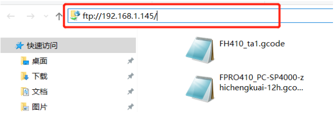
(2) FTP network. Enter the PRINTER's IP address in the window folder address bar on the computer side, and transfer the G-code file to the printer through the network for the printer to read.
¶ 5.5.3 Import the Printing File
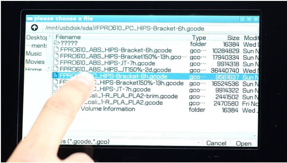
1. First select the location of the print file. Select the location of your files, such as U disk (USB) or File Transfer Protocol (FTP), from the drop-down bar in the upper right corner of the screen.
2. Click the open file icon in the lower left corner of the screen, and the list of printed files will pop up;

3. Select the required printing file, and then click "Open" to load the printing file. If U disk (USB stick) is used to import, after loading the printing file, the USB disk can be unplugged without affecting the printing.
¶ 5.5.4 Printing Process
¶ 5.5.4.1 Main process of printing
Click the "Start" button on the screen to start printing. The printing molding process is divided into four steps: "preheating - printing - heat maintaining - cooling".
1. Preheating. Preheat the printing platform and chamber before printing begins. Preheating temperature and preheating time are the platform temperature, chamber temperature and preheating time of the left nozzle material set on the Material Interface of the printer (because the material is different from that in the Gcode, it is necessary to confirm whether the material setting on the Material Interface is consistent with that in Gcode). When the platform temperature and chamber temperature are close to the target value, start the preheating timing;
2. Printing. When the preheating time is over, the printer begins to read the G-code file and perform formal printing.
3. Heat maintaining. After printing, the nozzle is cooled, and the printing platform and chamber remain at high temperature. The specific values of the heat maintaining temperature and duration are based on the platform maintaining temperature, chamber maintaining temperature and duration of the left nozzle material.
4. Cooling. After heat maintaining ends, the printer enters the cooling step, with the chamber naturally cooled first. When the temperature drops to Active cooling temperature, the Active cooling function of the printer will be started. The Active cooling blower will blow the cooling air into the printer's chamber until the chamber temperature drops below 50℃.
¶ 5.5.4.2 Modification of preheating time and heat maintaining duration
During the printing process, the preheating time and heat maintaining duration can be modified.
1. Click the extension button on the left of the Print interface to display the modification interface of preheating time and heat maintaining time;
2. Turn on or turn off by checking “Preheat” and “Maintaining”.
3. Modify the time by operating "-"/" + "or dragging the scrollbar, and finally press the “Change time” button to save the changes.
Note: Before printing, the preheating time can be turned off or reduced only if the chamber has been kept warm for a long time, insufficient preheat time will affect the printing result.
¶ 5.5.5 The Setting of Printing Parameters
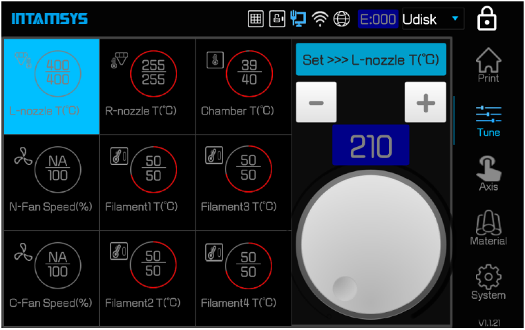
You can adjust the following process parameters of the printer in the Tune interface: left nozzle temperature (L-nozzle), right nozzle temperature (R-nozzle), chamber temperature (Chamber T), Nozzle cooling fan speed (N-Fan Speed), Chamber active cooling fan speed (C-Fan Speed), filament chamber temperature (Filament T).
The parameter adjustment steps are as follows:
1. Click the icon to modify the parameters and make it highlighted;
2. Click "-"/" + "on the right side or rotate the knob below to modify the parameter value, and the specific value will be displayed in the box;
3. Click Set button to complete the setting of this parameter.
¶ 5.5.6 Printing Alarm
If the printer detects a fault that could affect the print, a warning is given on the display. Depending on the severity of the warning, the alarm status button will change to yellow, orange, or red.
Pressing the alarm status button will open a dialog box indicating the cause of the alarm. The dialog box will contain information related to the cause of the alarm.
In some cases, an alarm will prevent you from printing and the printer will need to be corrected before it can print. Various warnings may be displayed as the printer performs the printing task, and some may pause or abort the printing. Depending on the severity of the warning, you may or may not recover your printing.
See 8. about troubleshooting for the list of fault alarms and handling methods.
¶ 5.5.7 Pause Printing
During printing, the pause button in the Print interface is in an optional status. The printer can be paused automatically, or it can be paused manually using this button.
¶ 5.5.7.1 Automatic Pause
1. When orange alarm is detected (see the orange alarm list in 8.1 for details), an automatic pause command will occur;
2. After the path in the cache is completed, the Z-axis platform decreases slightly, the nozzle stays in place and stops heating, the chamber temperature remains unchanged, and an alarm dialog box pops up to indicate the reason for the paused status;
3. After you need to correct this alarm, click "Clear" button to Clear the alarm;
4. To resume printing, press the start button in the interface of Print. The recovery command is sent to the printer instructing it to resume printing.
¶ 5.5.7.2 Manual Pause
1. When the pause button is pressed, a manual pause will occur;
2. After the path in the cache is completed, the Z-axis platform decreases slightly, the nozzle stays in place and stops heating, and the chamber temperature remains unchanged;
3. To resume printing, press the start button in the interface of Print. The recovery command is sent to the printer instructing it to resume printing.
¶ 5.5.8 Terminate Printing
When the Print task is started, the stop button within the Print page is in an optional status. The printer can be terminated automatically, or it can be terminated manually using this button:
¶ 5.5.8.1 Automatic Termination
When the red alarm occurs (see 8.1 for a list of red alarms), automatic termination will occur. When the printer receives the termination instruction, the nozzle, platform, and chamber heating functions will be turned off, and the XY axis will be reset to zero.
¶ 5.5.8.2 Manual Termination
A manual pause occurs when the stop button is pressed. When the printer receives a termination command, a dialog box is displayed to confirm or cancel the termination. Press the confirmation to terminate. When the printer receives the termination instruction, the nozzle, platform, and chamber heating functions will be turned off, and the XY axis will be reset to zero.
¶ 5.5.9 After Printing
After the printing is completed, the print head returns to zero and stops, and the printing progress on the screen will show 100%, indicating that the printing process has been completed. The printer's platform and chamber’s temperature may or may not be maintained by default.
To remove printed part from the printer:
1. Unlock the door and open the front door of the chamber. If you want to end the heat maintaining, remove the checkbox from Maintaining, and the front door and top cover are unlocked; If you still want to keep warm, click the lock button on the status bar of the screen to unlock the front door and the top cover.
2. Click the Axis interface and click the "Z↓_" button to lower the platform to the bottom. At this time, the platform will drop to the bottom of the chamber for easy taking out the buildsheet;
3. Click the vacuum adsorption button on the screen to deactivate the vacuum adsorption function. Then put on gloves and bring out the buildsheet and printed part;
4. After the printed part is cooled, carefully peel the printed part from the buildsheet with a spatula or directly remove the buildsheet from the vacuum adsorption platform.
5. Remove supporting material from printed part.
¶ 5.6 Change printer default Settings
¶ 5.6.1 Modify the System Date and Time
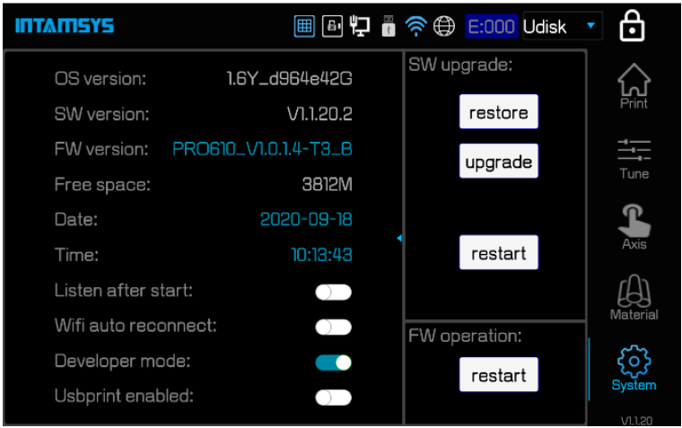
The system time of the printer will not be updated according to the local time zone, so it needs to be modified by the user. Click Date /Time on the interface of System, and the Date and Time modification box will pop up. After the modification is completed, exit the modification box and it will take effect.

¶ 5.6.2 Turn on/off Allows Network Remote Access
Listen after Start: It is set to allow remote access automatically after the system restarts.
Click the switch on the right of Listen After Start on the interface of System to start/close. The blue color shows "On". You can also manually click the "Listen" button on the remote printing service interface to start manually.

¶ 5.6.3 Turn Developer Mode on/off
Developer mode refers to the mode in which the printer is open to developers. It is mainly used for debugging of the printer and does not need to be enabled during normal printing. In developer mode, enabling developer mode can be customized to send G-code and open Logo for troubleshooting.
Click the switch on/off on the right side of the Developer mode on the System interface, and the blue color is on.

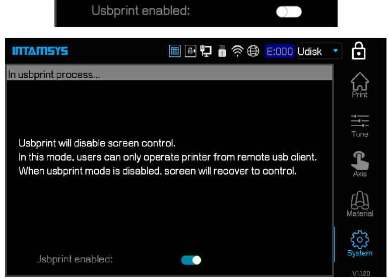
¶ 5.6.4 Turn on/off USB Print Mode
USB Print enabled (USB Print mode), which enables remote serial port direct printing through the USB serial port on the smart panel. In the case of enabling, the motherboard will interrupt communication with the screen and switch to USB serial port device communication. It is used for external computers to directly connect the printer with USB serial port for printing. When using this mode, it needs to be turned on; when not using this mode, it must be turned off; otherwise, it will affect the printing of other modes.
Click the switch on/off on the right of the USB print enabled on the System interface, and the blue color is on.
¶ 5.6.5 Filament Chamber Auto Heat
Material Chamber Auto Heat refers to the automatic heating function of Material chamber Auto heating. After activated, the filament chamber will automatically heat and control the temperature up to the material pre-selected level.
Click the switch on the right side of the Material Chamber Auto Heat on the interface of System to activate/deactivate, and the blue color means as activated.

¶ 5.6.6 Lock the Front Door and Top Cover
Door lock enabled means to open the front Door and the top cover.
Click the switch on/off on the right of Door lock enabled on the interface of System (System), and the blue color is enabled. You can also turn it on/off by clicking the lock icon on the status bar of the screen, with blue on.

To protect the user, the front door and top cover will be locked when the printer starts printing or when the chamber is heated, and will not be able to be opened. If forced unlocking is required during this process, click the lock button to unlock the front door and top cover.
Note: Do not put your hands into the chamber and above the top organ type shield after forced unlocking to prevent burns or clips.
¶ 5.6.7 Liquid Cooler Control
Liquid cooler control refers to the opening/closing of the Liquid cooling system.
Click the switch on/off to the right of Liquid cooler control on the interface of System (System), and the blue color shows "on".
The liquid cooling function will automatically open under the conditions of nozzle heating or chamber heating, and automatically close at a certain temperature. This button is used to force on/off the liquid cooling system. Do not operate this button in normal use.

¶ 5.6.8 Motor Enabled
Motor enabled refers to the X axis, Y axis, Z axis, extrusion Motor and auxiliary filament feeding Motor on/off.
Click the switch on/off on the right of the Motor enabled on the System interface, and the blue color shows "enabled".
Blue means all motors are powered on, grey means all motors are powered off. After it is closed, each motor can be driven freely by hand to facilitate equipment maintenance.

¶ 5.6.9 Auto-leveling Enabled
Automatic leveling enabled, that is, turn on the automatic leveling function of the printer. Compensation will be implemented according to the result of automatic leveling during the printing process.
Click the switch on the right side of the automatic leveling enabled interface to turn it on/off. The blue color shown is the activation. This function must be turned on during printing process in order not to affect the print result.

¶ 5.6.10 Screen Lock Password
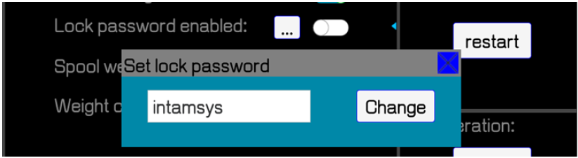
Lock password enabled, that is turn on the lock password enabled function of the printer. When this function is enabled, click the "lock screen" button to enter the screensaver, and input the password to re-enter the operation screen.
Click the right side button to turn on/off Lock Password enabled function on the System interface, and the blue color shown is the activation. Click ‘’…'' to enter the password modification interface. The default password is "intamsys".
¶ 5.7 Printer Status
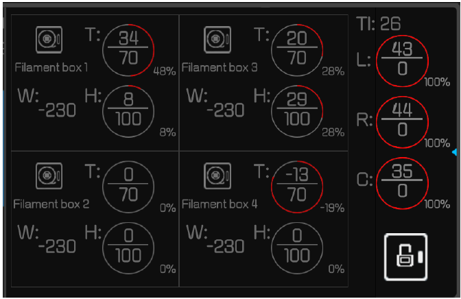
¶ 5.7.1 Temperature and Humidity Status
The temperature and humidity status of the printer can be viewed in real time on the Print interface.
L: The target temperature and real-time temperature of the left nozzle;
R: The target temperature and real-time temperature of the right nozzle;
C: The target temperature and real-time temperature of the chamber;
T: The target temperature and real-time temperature of the filament chamber;
H: Real-time humidity of the filament chamber
¶ 5.7.2 Filament Status
The status of the remaining filaments in the filament chamber can be viewed in real time on the Print interface.
W: The remaining weight of filament of each nozzle, in which 1 and 2 correspond to the left nozzle and 3 and 4 correspond to the right nozzle;
¶ 5.7.3 The State of the Liquid Cooling System
The state of the coolant in the printer's internal cooling system can be viewed in real time on the Print interface.
Tl: The temperature of the coolant in the liquid cooler.
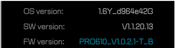
¶ 5.7.4 Software Version
Software versions can be accessed through the System interface.
OS version: Operating system version;
SW version: Screen version;
FW version: Firmware version.
¶ 6 Leveling and Calibration
This chapter describes the leveling and calibration method for operating FUNMAT PRO 610 HT.
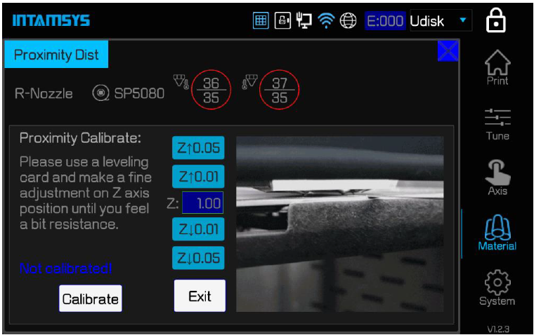
¶ 6.1 Trigger Distance Calibration
The leveling sensor is mounted on the right printing head, and the accuracy of its trigger distance calibration directly affects the accuracy of automatic leveling. The main purpose of trigger distance calibration is to calibrate the distance between the nozzle and the printing head sensor. Calibration is generally done once after the delivery of equipment, except when the printing head is repaired or replaced.
1. Click the "Trigger Distance Calibration" button on the Material Interface to enter the Trigger Distance Calibration Interface.
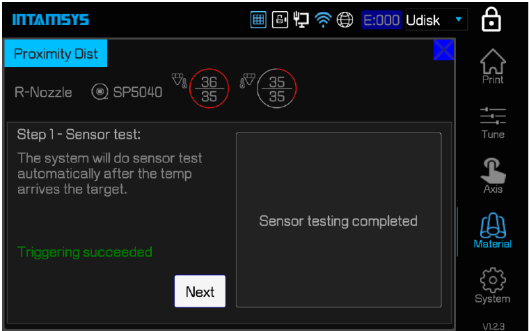
2. First, the printer will automatically perform triggering test of the sensor, and the printer will automatically test. After the test passes, the screen will display Triggering succeeded, and click Next;
3. Operate as the guide on the screen. Place the feeler between the nozzle and the glass of the printing platform (thickness: 0.2mm). Click the coarse adjustment button "Z↑0.05"/" Z↓0.05 " or fine adjustment button "Z↑0.01"/" Z↓0.01 " on the screen to adjust the rise/fall of the Z-axis so that the distance between the nozzle and the glass of the platform is just enough to fill the feeler; Take out the feeler, click the "Calibrate" button to complete trigger distance calibration, and click "Exit".
¶ 6.2 Automatic Leveling and XYZ Deviation Calibration
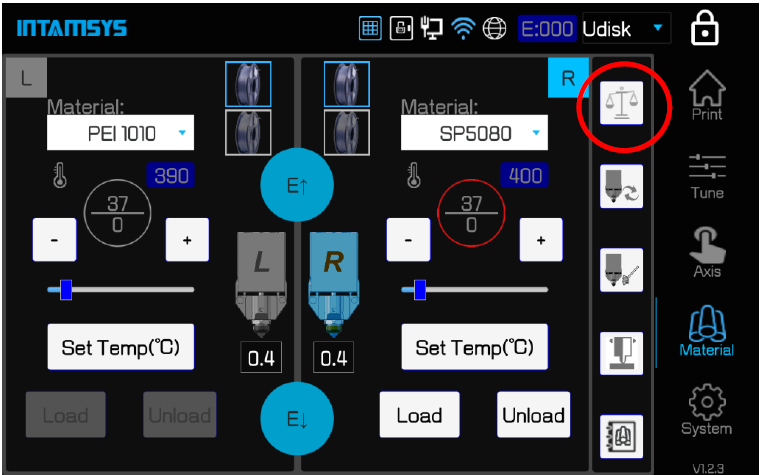
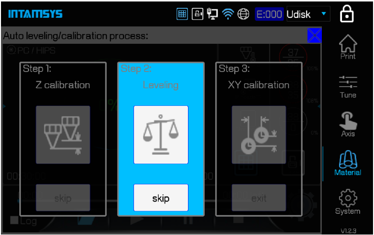
In the Material interface, click the "Balance" button to enter the automatic adjustment and XYZ offset calibration interface. The three steps from left to right are Z Calibrate, Leveling and XY calibrate.
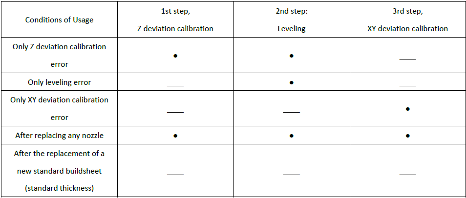
Any one or more of these steps can be performed optionally, but the three steps from left to right must be performed sequentially, and unnecessary steps can be clicked on the Skip button below the icon.
After the different operations, the following table shows the user how to selectively do the steps.
Note:
The cleaning degree of the nozzle directly affects the accuracy of calibration and automatic leveling, so before the calibration and automatic leveling, the heating surface of the nozzle should be cleaned.
When performing all adjustment and calibration steps, the buildsheet must be replaced with PC board to facilitate printing calibration and protection of the nozzle;
When performing all the adjustment and calibration steps, the vacuum adsorption of the buildplate must be kept open.
¶ 6.2.1 Z Deviation Calibration
The main purpose of z-axis offset calibration is to calibrate the deviation of the left and right nozzles in the Z direction. Please take out the special z-offset calibration dial indicator equipped with the machine and perform calibration according to the prompts on the screen.
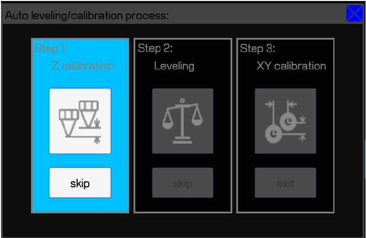
1. Click the Z calibrate (Z Offset Calibration) icon, a prompt box will pop up to prompt cleaning the printing platform. If it has been cleaned up, click "OK" to officially enter the Z-offset calibration operation;
2. First, calibrate the left nozzle, and the nozzle will be moved to a certain height from the buildsheet. Adjust the dial indicator to mm unit, place the dial indicator between the left nozzle and the buildsheet according to the prompts on the screen, and click the "ZERO" button on the dial indicator. Note that force should be exerted in the horizontal direction when clicking the button to avoid the effect of force in the vertical direction on the ZERO return result. Then click the "Next" button.
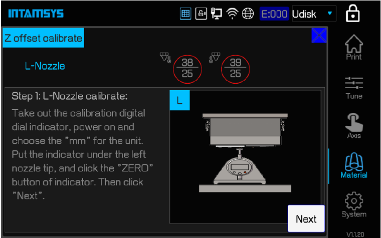
3. The printing platform will first descend to switch to the right nozzle and then rise to make the right nozzle contact the dial indicator. At this point, the value displayed on the dial indicator is the Z-offset value of the left and right nozzles, which is input into the dialog box on the printer screen, and then saved.
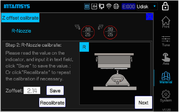
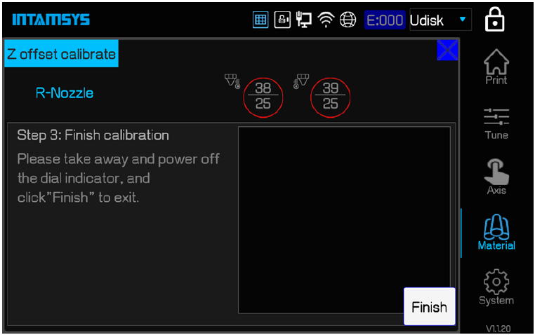
4. After calibration, take out the dial indicator and close it.
¶ 6.2.2 Automatic Leveling
Automatic leveling is mainly used to measure the position of three points on the platform by means of a leveling sensor mounted on the right printing head. The printer determines the relative position of the printing buildsheet and XY motion plane by itself, and compensates the rise or fall of z-axis in real time during printing. Even if the print buildsheet has a certain tilt Angle can also be achieved through compensation printing.
1. Click the icon of Leveling, a prompt box will pop up to prompt the cleaning of the printing platform, chamber and nozzle to prevent interference with Leveling. If it has been cleaned up, click "OK" button to officially enter the automatic leveling operation;
2. First, the printer will automatically perform triggering test of the leveling sensor, and the printer will automatically test. After the test passes, the screen will display Triggering succeeded, and click Next;
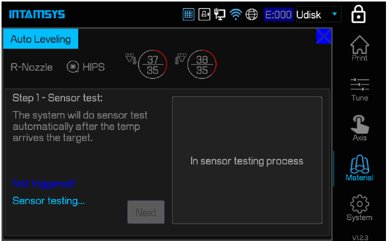
3. Click Auto Level button to prepare for the official automatic leveling;
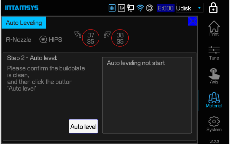
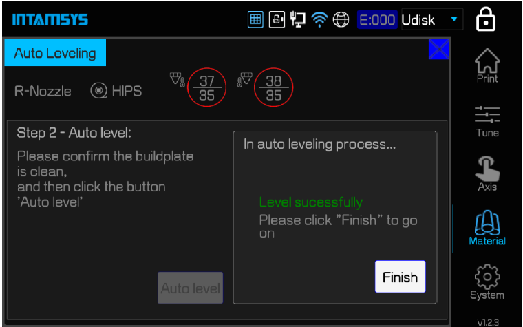
4. When in automatic adjustment, the nozzle will detect 3 points on the platform. After completion, the screen prompts automatic leveling success. It will also prompt you to clean the chamber. If you have finished cleaning, click Finish. The platform will drop to the bottom of the chamber and then return. Automatic leveling ends at this point.
¶ 6.2.3 XY Offset Calibration
The main purpose of the XY offset calibration is to calibrate the deviation of the left and right nozzles in the X and Y directions, and the deviation value is obtained from the actual printed calibration model.
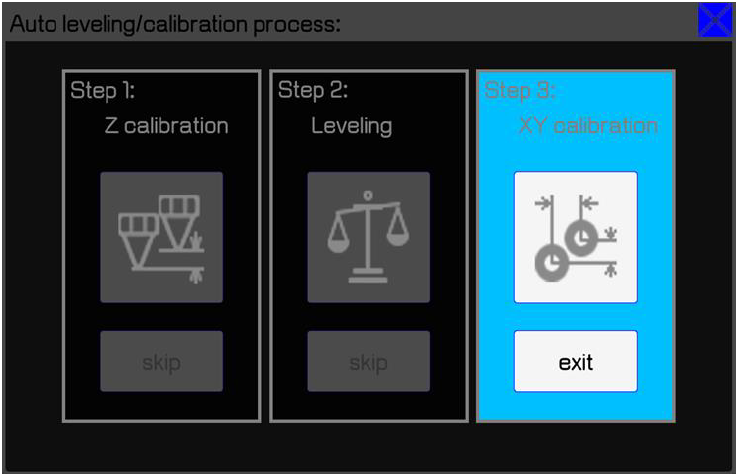
1. Click XY Calibrate (XY offset calibration) icon, prompt to confirm whether the material of left and right printing heads has been loaded, and prompt to clean the printing buildplate. Click Print button to start the calibration model printing. (If the XY deviation value is known, no need to click Print button, directly click Skip button, and then enter the X offset value and Y offset value respectively);
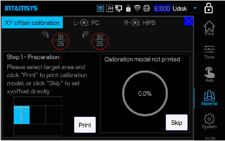
2. The printer will print the model ruler with the left head and the right head respectively. After the printing is finished, click (Next) button, and the head will move to the upper left corner of the platform for easy reading of the ruler. Take down the PC buildsheet printed with reading rulers, read the X offset value and Y offset value respectively, and click "+"/" - "button to enter the value.
The X deviation value should be obtained by reading the horizontal ruler, as follows:
(1) Take the model printed by the left nozzle as the reference, and read the model scale printed by the right nozzle;
(2) First, determine whether the center line of the right nozzle model is located to the left or right of the center line of the left nozzle model. If on the left, take the value of "-"; if on the right, take the value of "+";
(3) Find the most aligned scale line of the two models, count from the middle line to this scale line, and the value is denoted as N;
(4) Enter the "N" value in the input box.
The Y offset value should be obtained by reading the numerical direction scale, as follows:
(1) Take the model printed by the left nozzle as the reference, and read the model scale printed by the right nozzle;
(2) First, determine whether the center line of the right nozzle model is above or below the center line of the left nozzle model. If at the bottom, take the value of "-"; if at the top, take the value of "+";
(3) Find the most aligned scale line of the two models, count from the middle line to this scale line, and the value is denoted as N;
(4) Enter the "N" value in the input box.
For example, the following figure shows the ruler printed by an XY deviation calibration. After reading, the X deviation value should be "+6" and the Y deviation value should be "-6".
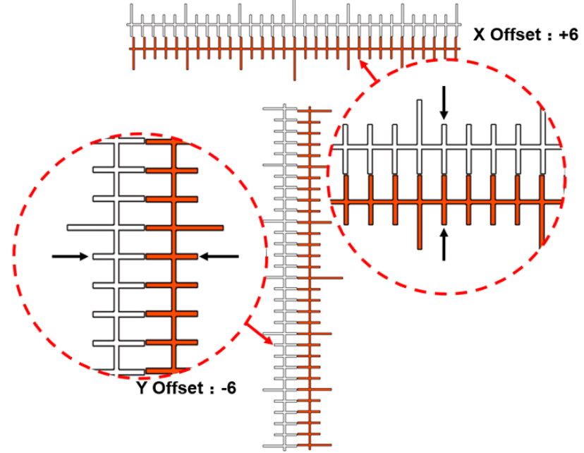
Note: Deviation value 1 represents the actual deviation of 0.05mm.
If after reading the printed scale, it is found that the middle line of both horizontal and vertical printed scales are far apart and other scales are difficult to coincide, it indicates that the XY deviation is beyond the measurable range of the scale (the maximum scale range is ±15, i.e. ±0.75mm). Take the following steps:
(1) Firstly, observe the position of the center line of the right nozzle model relative to the center line of the left nozzle model, and determine the deviation direction "-"/" + ";
(2) Then set the deviation value to the maximum value and click the "OK" button;
(3) Perform XY deviation calibration again and print the test model until the confirmed deviation value is read.
¶ 6.3 Material Weight Calibration
As shown in the figure, the weighing sensor in the filament chamber is loaded with material shaft, material spool and material. In order to obtain the accurate weight of material, the weight of material shaft and material spool needs to be deducted.
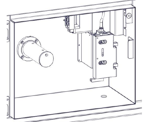
The weight calibration steps of materials in the filament chamber are as follows:
1. On the System interface, click The Weight Calibration button to pop up the calibration box.
2. First proceed with Zero calibration. Remove all materials from the filament chamber and leave only the material spool. Click Calibrate button on the right of Zero calibration;
3. The Sample weight is then calibrated for a second time. Install calibration weights of known weight (such as 1,000g) on the material spool respectively, and click Calibrate button on the right side of Sample Weight respectively.
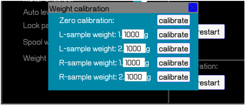
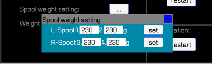
4. Enter the weight of the empty spool in the input box of Spool Weight Setting, and click the set button to save it.
¶ 7 Maintenance
Correct and regular maintenance will not only prolong the service life of the machine, but also greatly improve your printing success rate and printing effectiveness each time. Maintenance tasks must be performed on a regular basis to ensure that the system is in optimum working condition. This chapter describes the various maintenance tasks that users need to implement on FUNMAT PRO 610 HT.
¶ 7.1 Maintenance after Each Print
¶ 7.1.1 Clean Printing Vacuum Platform
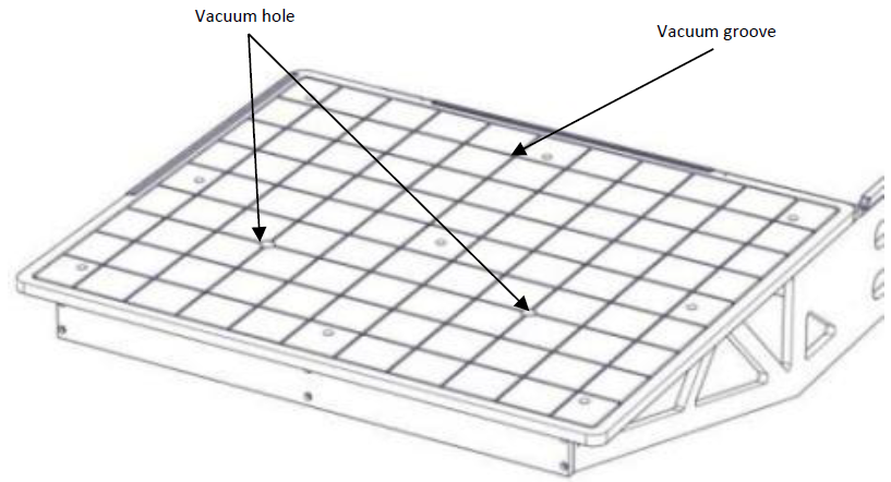
The buildplate platform is a mechanism for placing and adsorbing buildsheets. If there are debris and filaments on the buildplate platform, it will affect the adsorption of buildsheets, causing problems such as vacuum alarm or deviation of the buildsheets in the printing process. Therefore, it needs to be cleaned timely.
1. Clean the buildsheet first
After the chamber is reduced to room temperature, clean up the waste material and debris on the buildsheet surface to avoid debris falling into the groove of the buildplate when the buildsheet is removed.
2. Then remove the buildsheet
Close the vacuum, lift one corner and pull it out with both hands. Avoid the scrap on the buildsheet falling into the vacuum tank of the buildplate.
3. Finally clean the buildplate
Use a brush to clean the grooves of the vacuum platform and clean outwards from the middle of the vacuum platform. Pay attention to avoid the vacuum hole to prevent blockage of the vacuum tube. Use a vacuum cleaner when necessary.
¶ 7.1.2 Clean the Buildsheet
Use a tool such as spatula to separate the model from the print buildsheet. The remaining materials on the buildsheet or the materials dropped during the printing process should be cleaned in time before each printing to avoid affecting the next printing.
Note that the buildsheet should not be excessively bent or the vacuum adsorption will be affected.
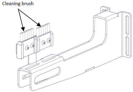
¶ 7.1.3 Cleaning Nozzle Brush
After one printing, the nozzle brush may stick to some materials. Please carefully clean up the materials and other sundries adhered to the nozzle brush. If more copper wire is found to be bent, a new nozzle brush should be installed.
¶ 7.1.4 Clean the Debris and Residue Collection Box
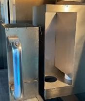
Lower the printing platform to an appropriate height, remove the collection box and clean it accordingly.
¶ 7.1.5 Clean the Printing Chamber
Check and clean the printing chamber, and remove the remaining debris and residue.
¶ 7.2 Weekly Maintenance
¶ 7.2.1 Clean Printing Chamber Interior
1. Use a vacuum cleaner and a sharp knife to clean the waste and residue in the buildplate, the bottom of the chamber, etc.
2. If necessary, wipe the printing space with a cleaning cloth and alcohol.
¶ 7.2.2 Clean Print Nozzle Component
1. Check the usage of the nozzle.
- Test wear and replace nozzles as needed.
- Nozzle blockage test. Click the "Material" button, and then click the "Set Temp(℃℃)" button to heat the nozzle. After the temperature rises to the specified temperature, long press the button "E↓" and observe the extrusion condition of the nozzle. According to the actual situation, choose a tool to dredge the nozzle or change the nozzle. (Note: After the nozzle is heated, heat insulation gloves should be worn to prevent scalding.)
2. Detect the residual material in the nozzle
If there is leakage of material, and through the gap into the housing or cover the nozzle in the housing clearance, it is necessary to remove the housing for cleaning. Hold the printing head cover with one hand, open the spring clasp with the other hand, and remove the printing head cover. According to the situation of material penetration, use tools to clean.
3.The system will automatically use the nozzle cleaning unit to clean the nozzle before and during each printing. However, the nozzle may accumulate debris that the automatic cleaning process fails to remove. Use a copper brush to clean the nozzle manually.
¶ 7.2.3 Clean up the Filament Chamber
1. The feed gear of the auxiliary filament feeding device is in frequent contact with the feed filament, resulting in debris and a little residue in the gear. Clean the debris at the root of the tooth with a sharp needle.
2. There will be crumbs in the filament chamber. After using the vacuum cleaner, wipe the residual dust with a cleaning cloth and alcohol.
¶ 7.3 Monthly or Quarterly Maintenance
¶ 7.3.1 Magnetic Suction Dustproof Net Cleaning
It is recommended to clean the dustproof net once a month (20-30 days). If the environment is dusty or the dustproof net is dirty, clean it in time and increase the cleaning frequency according to the situation.
1. The location of dustproof net is shown in the picture below. The rear of the equipment (electrically controlled fan dust net X1, water cooling machine dust net X3); Left side of equipment (bottom dustproof net X3);
2. After disassembling the sheet metal at the back and bottom of the equipment, you can remove the square screws. Dustproof net can be taken out on both sides of liquid cooling machine.
3. Dustproof net cleaning: clean the floating ash with clean water after taking off, and use it again after drying.
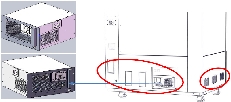
¶ 7.3.2 Ball Screw and Guide Rail Cleaning
Good lubrication is very necessary when using ball screw and guide rail. Without sufficient lubrication, the friction between steel ball and rolling surface will increase during operation, which may shorten the life of the screw. Therefore, it needs to be maintained regularly.
The equipment needs to be maintained in three places: XYZ axis, see the figure below.
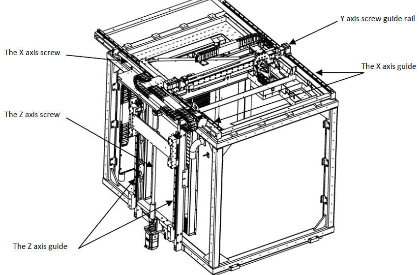
The maintenance method is as follows:
1. Clean surface: dust generated in the running process of guide rail and ball screw or dust volatilized from heated filament will be attached to high temperature grease. Clean it with dust-free cloth (pay attention to ball thread groove and guide groove).
2. If there is an air gun, blow out the grease from the oil injection hole, nozzle and screw. If no air gun, use a dust-free cloth to clean these gaps as clean as possible.
3. Fill the grease from the nozzle and other greasing devices until the old grease is discharged.
4. Run in after filling, excess grease will be discharged, remove the discharged grease before starting operation.
5. After repeated operation for many times, apply high temperature grease on the surface of ball screw and guide rail to protect the surface of screw guide rail.
- Note: The guide rail of the X and Z axis uses the C-Lube series of IKO, which is generally used once every 6 months, so the quarterly equipment is frequently used, it is recommended to add grease once every 3 months.
¶ 7.4 Annual maintenance
¶ 7.4.1 Replace the Short Liquid Cooling Pipe on the Printing Head Component
- Open the front door on the top and shut down the printer;
- Step on the ladder, wrap the quick connector of the main liquid cooling pipe with a cleaning cloth to prevent coolant leakage, and unplug the connector;
- Wrap the fixing nuts of the 4 short liquid cooling pipes with cleaning clothes, and then loosen and remove the pipes;
- Replace with new short liquid cooling pipes in turn, and manually tighten the fixing nuts. Do not tighten the nuts with tools to avoid over-tightening.
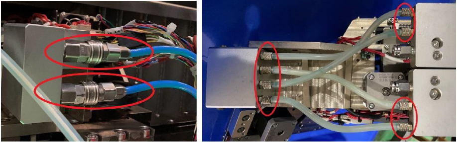
¶ 7.4.2 Replace the Filament Tubes
- Open the front door on the top and shut down the printer;
- Step on the ladder, press the fixed seat ring on the adapter with one hand and pull out the wire tube with the other hand;
- Remove the wire tubes from the adapters of the two Y-shaped pipes in the same way;
- Prepare wire tubes of the same length and reinstall them.
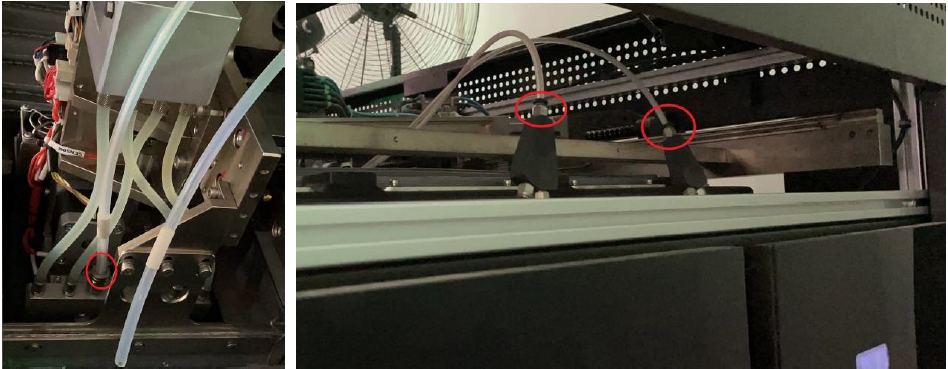
¶ 7.4.3 Replace the Coolant
- Prepare a container in advance to store the old coolant. Remove the rear lower cover of the printer, insert the drainage pipe into the quick connector, and wait until the coolant is completely drained.
- Remove the screws at the top of the small liquid level window. Insert the funnel, and fill coolant until the liquid level reaches the MAX line, and then re-tighten the cap.
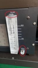
¶ 7.5 Maintenance as needed
¶ 7.5.1 Clean Printing Chamber Interior and Equipment Exterior
1. During the printing process, small amounts of dust will be generated from the heated filament, which will accumulate on the chamber door glass and door panel, the lighting lampshade and the vent. Clean them with a clean cloth and alcohol (or diluted isopropyl alcohol). Note, do not operate under high temperature to prevent scalding and other problems.
2. Sheet metal paint or acrylic and touch screen surfaces on the exterior of the equipment can be wiped with commercial glass cleaner or with general purpose cleaning cloth and alcohol.
¶ 7.6 Miscellaneous
It is recommended that your machine be thoroughly inspected by professionals before the expiration of the one-year warranty period to check whether the fans, heaters, liquid cooling unit and other components are still in normal status. If you find any abnormalities, please contact our local partner. These inspections may require the removal of protective parts and the placement of the devices to be inspected in an observable state, which poses a certain risk. Please be aware of safety.
The latest versions of machine firmware and screen software are available at:
https://www.intamsys.com/
Note:
- Do not use rough or highly alkaline products.
- Do not use detergent under direct sunlight or high temperature.
- Do not use scraper, razor blade or other sharp tools.
- Do not use gasoline, acetone, or carbon tetrachloride for cleaning.
- If a scratch occurs, a mild car polish can be used to eliminate or reduce minor scrapes.
- The glass on the oven door should only be cleaned with isopropyl alcohol. This prevents the glass from forming a film at high temperatures.
¶ 8 Troubleshooting
This chapter lists some of the types of failures that can occur during the printing process and the troubleshooting measures required after each failure occurs.
If you have any problems following this user manual, please contact customer support in your area.
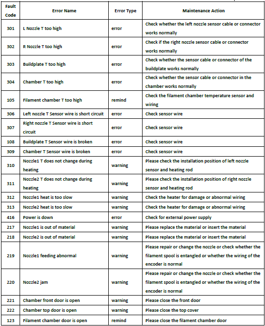
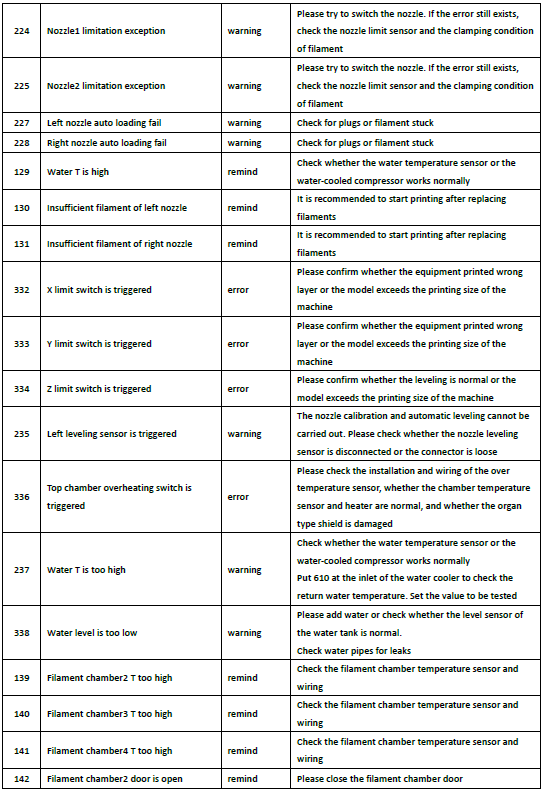
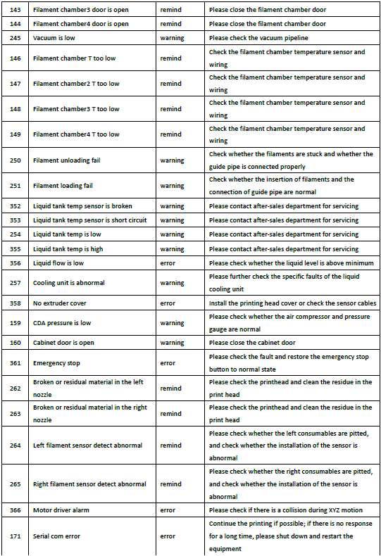

¶ 1. Cooling Unit
¶ 1.1 Display Screen Configuration
1. The main contents of the display screen are shown as the following figure, including work indication, stop indication, fault indication, heating indication, refrigeration indication, setting temperature, measured temperature, and real-time speed of the compressor.
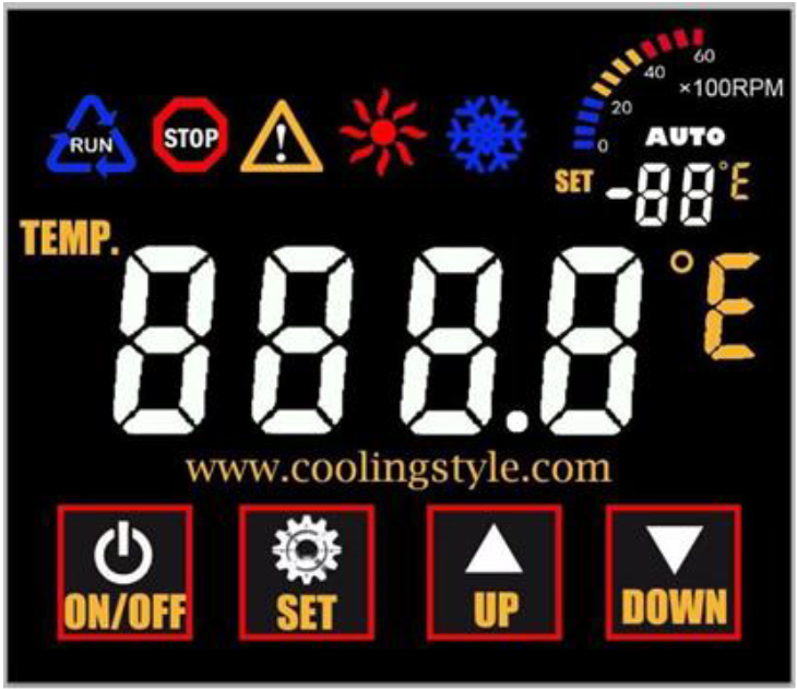

Work indication: When the light is on, it means that the chiller is in startup state (AUTO indicator is on);

Stop indication: when lit, it means that the chiller is in shutdown state (including shutdown and failure);

Fault indication: When lit, it means that the chiller is out of order or gives an alarm.

Heating indicator: when lit, it means that the chiller is in heating state;

Refrigeration indication: when lit, it means that the compressor is working and the chiller is in refrigeration state;
Compressor speed identification: shows the current speed of the compressor;
This logo has three functions: when working normally, it displays the set target water temperature; When the fault state is displayed, the fault code is displayed; The third function is to display the temperature when high/low temperature alarms are triggered.
Real-time water temperature: display accuracy is 0.1℃.
2. The display adopts capacitive touch buttons. Their main functions include switching machine operation and setting the water temperature in the water tank. The buzzer will emit a short "beep" sound when the button touch is effective, and will not respond when the button touch is invalid.