¶ X motor
¶ Steps:
a. Power machine off, and unplug main power cable. Use knob wrench (Figure 1.4-1) to remove the left cover.
b. use 3mm Allen-Key to loosen 3 screws and remove the triangle arm. Figure 6.5-1
c. Use 2.5mm Allen-Key to loosen 5 screws and remove the cover on the left side. Figure 6.5-2
d. Open the top door, use 2.5mm Allen-Key to loosen 4 screws and remove the left inner cover. Figure 6.5-3

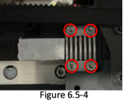
e. Now X motor can be seen. Use knob wrench to remove the right cover. Move X rail through Y axis to make the tension adjustment screw aim the hole on the left side cover (Figure 6.5-4). Then loosen the screw in the hole to release the tension.
f. Remove the 4 screws fixing the X blet clamp left beside extruder assembly. Figure 6.5-4 It is recommended to make a market sticker on the belt before loosen screws. Then, take the belt off the motor gear.
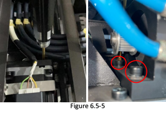
g. Unplug the cable to X motor, remove 2 screws with 3mm hex screwdriver that fixing the mount of X motor. (The purpose to remove belt is to get the rear screw available) Figure 6.5-5
h. Lower the mount with motor a bit and remove 2 screws of the clamp fixing cooling block. Use a bdlade or else to remove the glue and separate the motor and cooling block.
i. Take the mount with motor off machine, and replace the motor.
j. When do the recovery, notice the tension of belt. Make sure it is similar to what it was.