¶ Encoder, Nozzle Switch Sensor, Auto-leveling Sensor
¶ Steps:
¶ a. Encoder
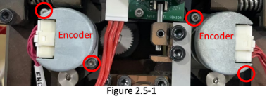
Follow 2.1 to take extruder assembly off machine. Remove the back cover. Locate the encoder and remove 2 screws with 1.5mm Allen-Key to take it off. Figure 2.5-1

¶ b. Nozzle Switch Sensor (L/R)
When switching nozzle, the flag in feed motor assembly will activate L/R switch sensor accordingly, thus machine knows switch done.
Follow 2.1 to take extruder assembly off machine. Remove the back cover.
Locate the 2 sensors. Unplug cable connectors and use 1.5mm Allen-Key to remove the screws and take it off.

¶ c. Auto-leveling Sensor
Follow 2.1 to take extruder assembly off machine. Remove the back cover.
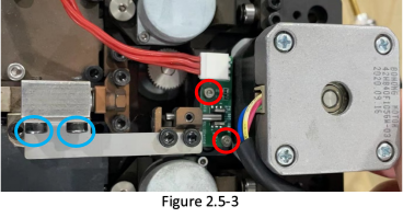
Locate the sensor. Unplug cable connector. Remove 2 screws with 2.5mm Allen-Key (Bule highlighted in Figure 2.5-3) to take sensor flag off. Then remove 2 locking screws (Red highlighted in Figure 2.5-3) with 1.5mm Allen-Key to take sensor off.

¶ d. Activating Rod height adjustment - Auto-leveling Sensor
Sometimes “E235 – Leveling sensor is abnormal” happens due to improper position of activation pin. Moving the pin up or down to correctly activate the sensor is needed.
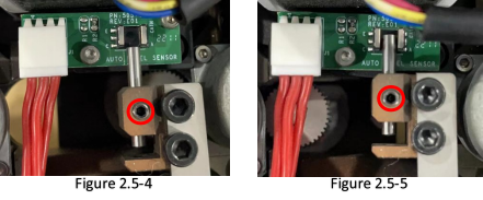
Manually move the feed motor assembly to lower right nozzle down, check the position of pin, it should be under the sensor, not activating the sensor. (Figure 2.5-4)
Manually move feed motor assembly again to lift right nozzle up, check the position of pin, the top of pin should be higher than the middle of sensor. (Figure 2.5-5)
Loosen or tighten the set screw to adjust the position of pin to meet the above 2 points.
