¶ 3.6 Base of Extruder, Leveling Sensor, Throat Cooling Fan, Choke Cooling Fan, Interconnection PCB of the Base
1. Disconnected the main power, take the extruder assembly off the machine. (It support hot plug)
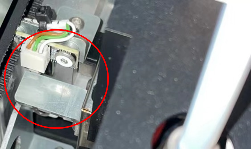
2. Remove 5 screws on L&R side of the metal cover of PCB with 2mm Allen-Key, and remove the cover. (Notice: the flag of X limit sensor is fixed by 2 of these 5 screws) Figure 3.6-1

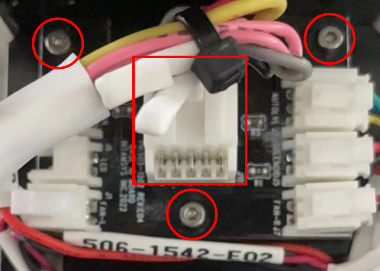
3. Unplug the cables on L&R edges of the interconnection PCB. Then, remove 3 screws on the PCB with 1.5 mm Allen-Key, lift the PCB up and unplug the main connection cable on it. Figure 3.6-2. The interconnection PCBs on L&R bases are different, they cannot be swapped.
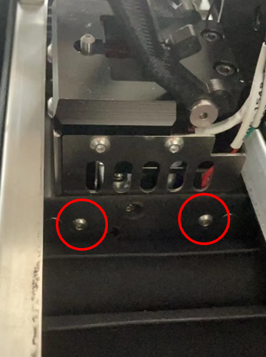
4. Remove 4 screws with 2mm Allen-Key to separate the base from L&R sides’ bellows shown in Figure 3.6 - 3
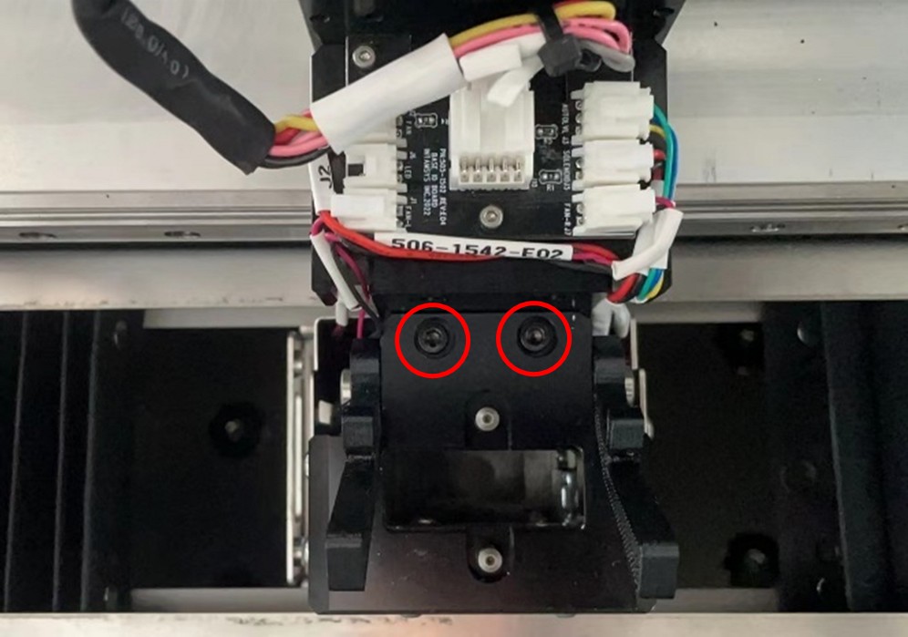
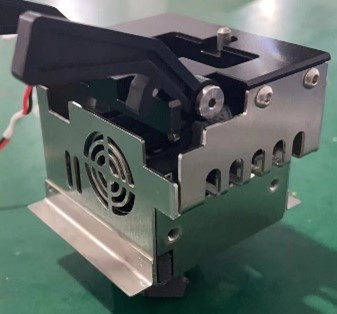
5. Remove 2 screws with 2.5 mm Allen-Key shown in Figure 3.6-4, then slide the base (Figure 3.6-5) towards left or right to take it out.
|
|
6. The leveling sensor assembly (Figure 3.6 - 6) is in the left side of the base of left extruder. Remove the 4 screws to take it off the base. Then, replace the sensor, electromagnet or else as needed.

7. Remove the related screws to take the specific fans off as needed. (the fan in the front is for cooling throat, the ones at the side and rear are for cooling filament)
8. Same way to deal with the base of right extruder assembly.
Notice: when install the flag of X limit sensor, make sure the flag can activate the sensor as well as not touching it. Figure 3.6-7
